Image forming device

a technology of forming device and recording medium, which is applied in the direction of printing, other printing apparatus, etc., can solve the problems of deteriorating image quality, slippage of drive shaft, and easy development of slack so as to reduce the influence of reverse-feed-prevented conveying roller and ensure the flatness of recording medium in recording section high precision

Inactive Publication Date: 2010-09-23
FUJIFILM CORP
View PDF15 Cites 16 Cited by
  • Summary
  • Abstract
  • Description
  • Claims
  • Application Information

AI Technical Summary

Benefits of technology

[0025]By setting the direction of curvature of the recording medium as above, the reaction force of the recording medium between the reverse-feed-prevented conveying roller and the second conveying rollers can be made even smaller, and influence on the reverse-feed-prevented conveying roller can be decreased.
[0026]According to the present invention a high precision of flatness of a recording medium in a recording section can be ensured.

Problems solved by technology

However, there are problems with such a method in that generation of longitudinal creases sometimes occurs due to tensioning the recording medium, and slippage of the drive shaft sometimes occurs due to influence from the conveying direction downstream side.
However, in the technology of Japanese Patent Application Laid-Open (JP-A) No. 2006-56655, since there is a strong gripping force employed at the downstream side of the recording section, slackness of the recording medium in the recording section readily develops when the feed speed at the upstream side is fast.
In addition, when the speed at the downstream side is fast, slippage is sometimes generated relative to the image face of the recording medium, this being a cause of image quality deterioration.
Also, since plural rollers are also required, this increases the number of components.

Method used


Image

  • Image forming device
  • Image forming device
  • Image forming device

Examples


first exemplary embodiment

[0037]Explanation will now be given of an exemplary embodiment of the present invention, with reference to the drawings.

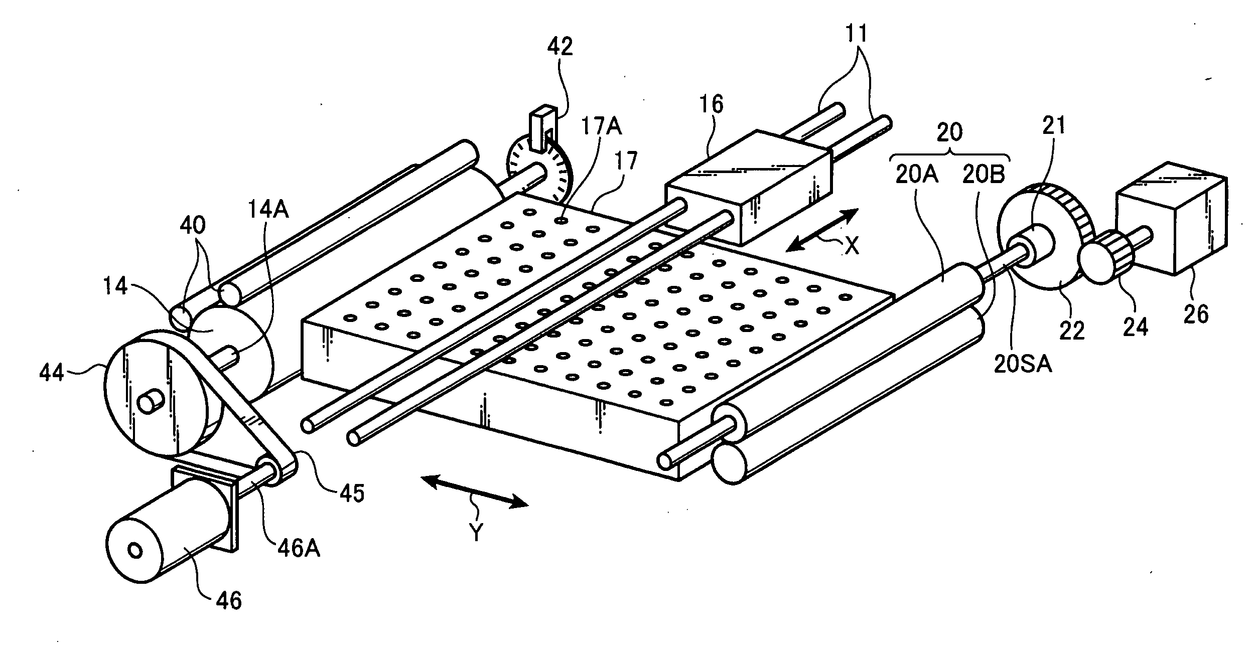
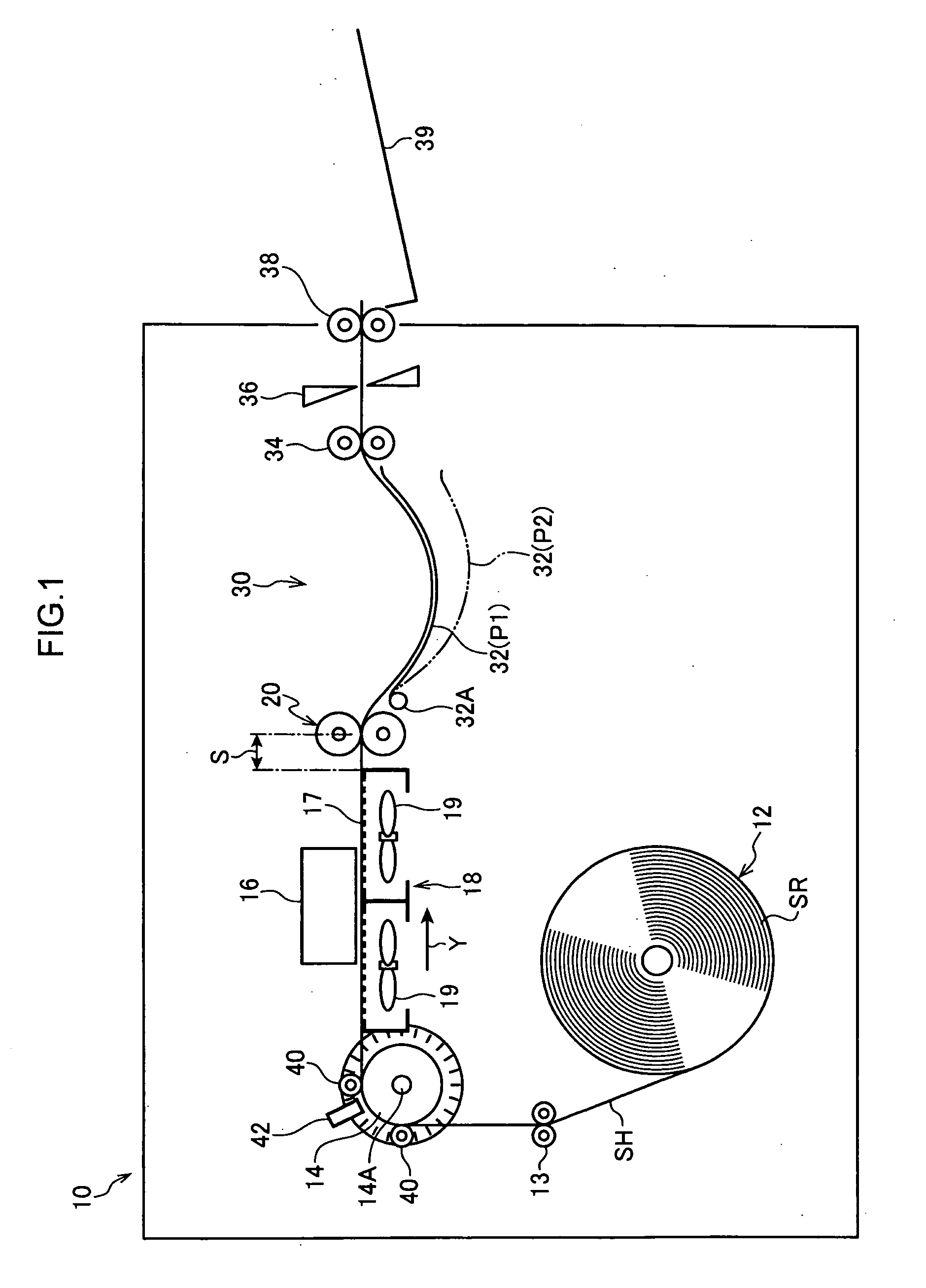
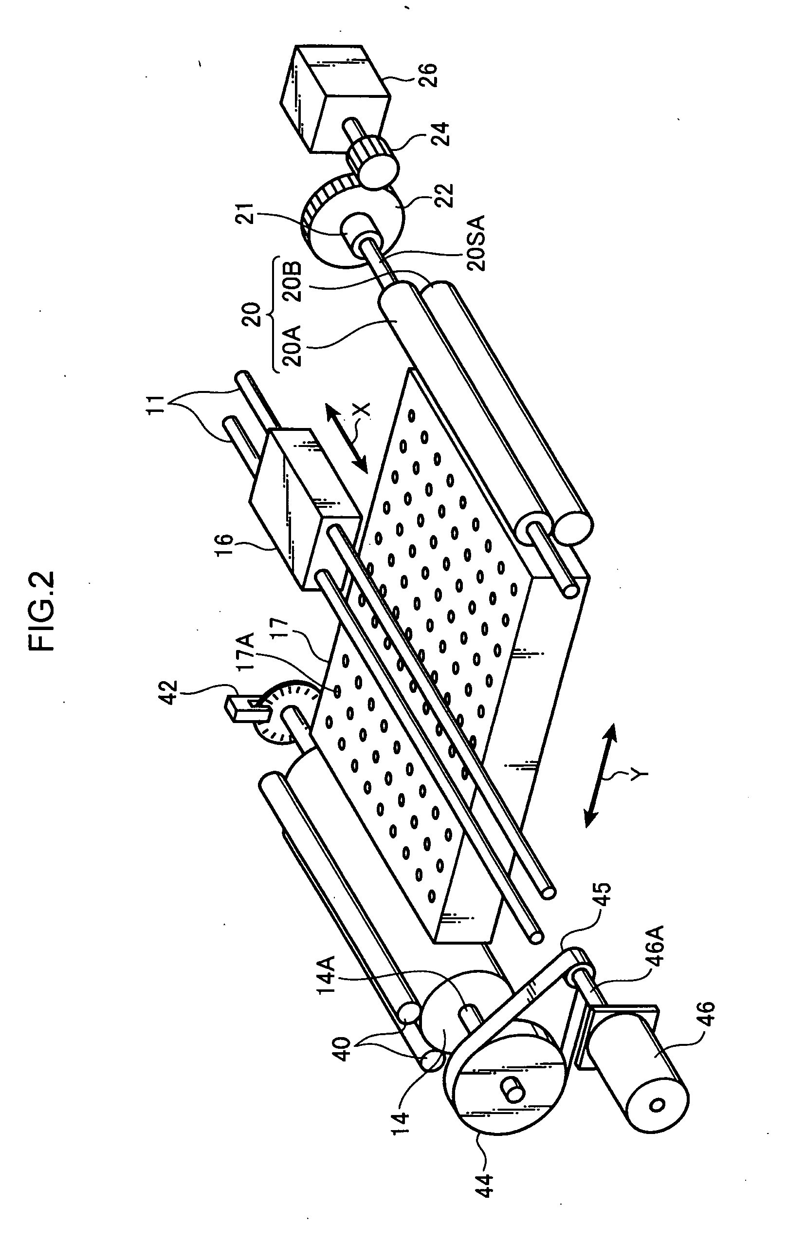
[0038]As shown in FIG. 1, an image forming device 10 according to the present exemplary embodiment is equipped with: a roll-paper feed section 12; a slow-scan roller 14; a recording head 16; an attraction image rendering section 18; first conveying rollers 20; second conveying roller 34; a cutter 36; a curved conveying section 30; discharge rollers 38; and a paper discharge tray 39.

[0039]The roll-paper feed section 12 is stocked, as a recording medium, with elongated recording paper SH wound into a roll shape to form a roll recording paper (continuous paper) SR. Examples of the recording paper SH include ordinary paper, inkjet recording paper that has an ink absorbing layer on both faces thereof, and the like. The roll recording paper SR is unwound toward the conveying direction downstream side, by a conveying roller 13 or the like, and is conveyed out as a web (in...

second exemplary embodiment

[0068]Explanation will now be given of a second exemplary embodiment of the present invention. The present exemplary embodiment is provided with an attraction image rendering section 50 in place of the attraction image rendering section 18 of the first exemplary embodiment. Since other parts of the configuration are similar to that of the first exemplary embodiment, the same reference numerals will be allocated thereto, and detailed explanation thereof omitted.

[0069]As shown in FIG. 7, the attraction image rendering section 50 of the present exemplary embodiment is equipped with a conveyer belt 52 and suction fans 19. The conveyer belt 52 is of an endless shape and is configured over the entire surface thereof with plural suction holes 52A for suctioning, as shown in FIG. 8. The conveyer belt 52 is entrained around belt rollers 54, 56. The belt roller 56 is disposed at the conveying direction downstream side and is rotationally driven by a non-illustrated motor so as to convey the r...


PUM


Abstract

An image forming device provided with: a recording head that renders an image by ejecting liquid droplets onto a recording medium; an attraction image rendering section having a liquid droplet reception flat portion disposed facing the recording head, the attraction image rendering section attracting the recording medium onto the flat portion and maintaining the flatness of the recording medium; an upstream side conveying section that feeds the recording medium out toward the attraction image rendering section; and a reverse-feed-prevented conveying roller disposed at the downstream side of the attraction image rendering section, the reverse-feed-prevented conveying roller being capable of friction-pushed rotation toward the conveying direction downstream side, nipping the recording medium and feeding the recording medium toward the conveying direction downstream side, and prevented from rotation toward the conveying direction upstream side.

Description

CROSS-REFERENCE TO RELATED APPLICATIONS[0001]This application claims priority under 35 USC 119 from Japanese Patent Application No. 2009-069986 filed on Mar. 23, 2009, the disclosure of which is incorporated by reference herein.BACKGROUND OF THE INVENTION[0002]1. Technical Field[0003]The present invention relates to an image forming device, and in particular to an image forming device that forms an image on a recording medium by ejecting a liquid onto the recording medium.[0004]2. Related Art[0005]Image forming devices that form images on recording media by ejection of a liquid, such as ink, are widely known. In such image forming devices, the recording medium is conveyed to directly below a recording head, and an image is rendered.[0006]In such image forming devices, since any non-uniformity in the separation distance between the recording head and the recording medium has an effect on image rendering, correction to maintain the recording medium in a flat shape is already sometimes...

Claims


Application Information

Patent Timeline
Patent Type & Authority Applications(United States)
IPC IPC(8): B41J2/01
CPCB41J11/0005B41J11/0085B41J15/04B41J11/70B41J11/06
Inventor KACHI, YASUHIKO
Owner FUJIFILM CORP
Why Eureka
Try Eureka