
Device and method for installing femoral prosthetic knee joint

a technology for prosthetic knees and knee joints, applied in joint implants, medical science, surgical saws, etc., can solve problems such as accelerated wear patterns or possible joint dislocation, loss of knowledge of previous tensions and orientation, and difficulty in the art of achieving correct alignmen

Active Publication Date: 2010-09-23
GHIJSELINGS IGNACE
View PDF43 Cites 39 Cited by
  • Summary
  • Abstract
  • Description
  • Claims
  • Application Information

AI Technical Summary

Benefits of technology

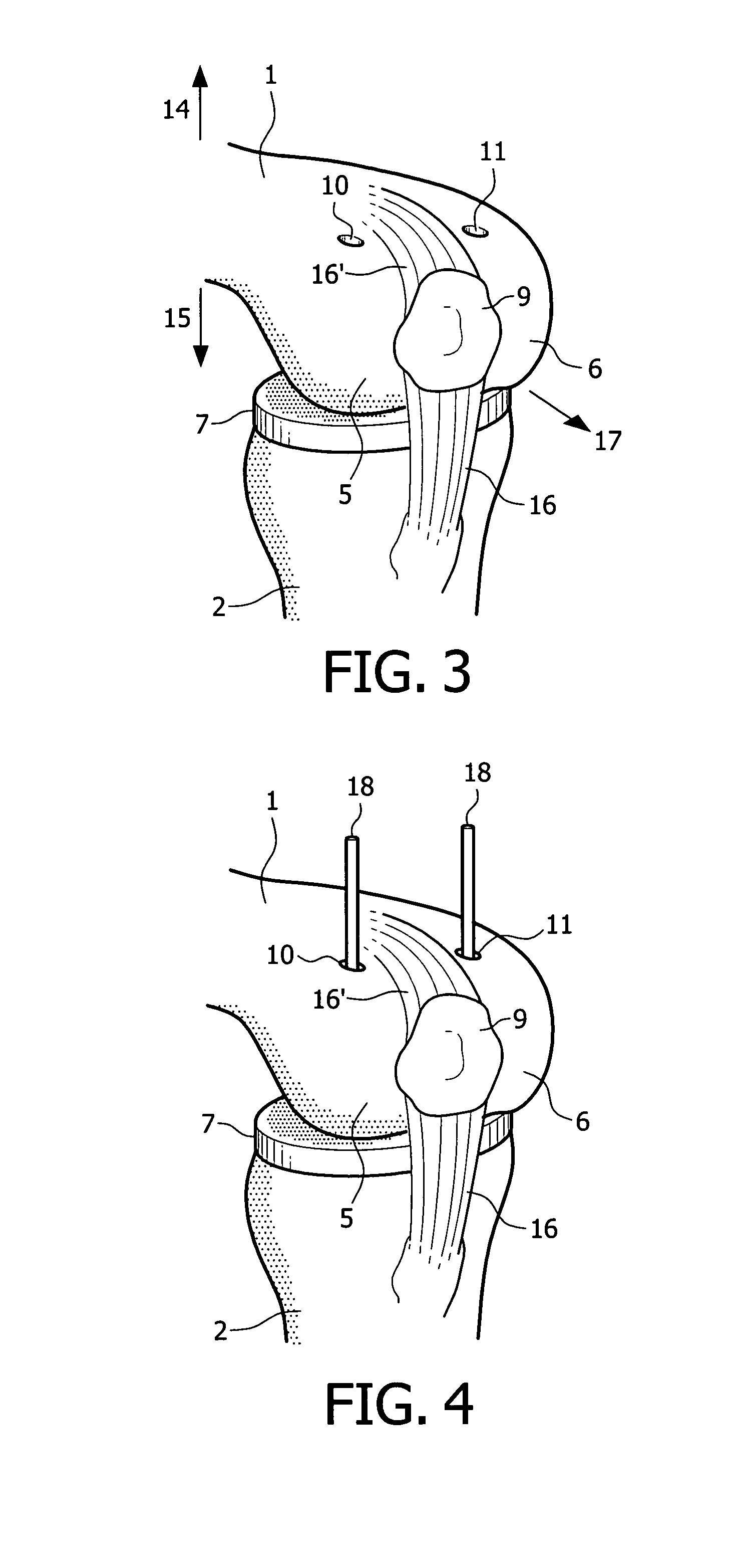
[0038]One embodiment of the present invention is a device (spacing means) for assisting prosthetic knee surgery by maintaining a correct flexion gap between the femur and tibia while the knee is in flexion, said device comprising at least one elongate member (18) of dimensions for introduction through a hole (10, 11) that passes from the anterior (14) end of a femoral condyle (5, 6) through to the posterior (15) end of said condyle (5, 6), which member is provided with an adjustable protrusion configured to protrude from the posterior (15) end of said condyle (5, 6) by an amount at least equal to the flexion gap (4).

Problems solved by technology

There is difficulty in the art with achieving the correct alignment of femoral cuts because cutting the bones requires effectively dismantling the joint so the knowledge of the previous tensions and orientation is lost.
When the cuts are incorrect, improper kinematics will arise as the joint rotates in use, and accelerated wear patterns or possible joint dislocation may occur.
Inadequate soft tissue balancing will lead to instability, pain and eventual failure.

Method used


Image

  • Device and method for installing femoral prosthetic knee joint
  • Device and method for installing femoral prosthetic knee joint
  • Device and method for installing femoral prosthetic knee joint

Examples


Embodiment Construction

[0090]Unless defined otherwise, all technical and scientific terms used herein have the same meaning as is commonly understood by one of skill in the art. All publications referenced herein are incorporated by reference thereto.

[0091]The articles “a” and “an” are used herein to refer to one or to more than one, i.e. to at least one of the grammatical object of the article. By way of example, “a pin” means one pin or more than one pin.

[0092]Throughout this application, the term “about” is used to indicate that a value includes the standard deviation of error for the device or method being employed to determine the value.

[0093]The recitation of numerical ranges by endpoints includes all integer numbers and, where appropriate, fractions subsumed within that range (e.g. 1 to 5 can include 1, 2, 3, 4 when referring to, for example, a number of pins, and can also include 1.5, 2, 2.75 and 3.80, when referring to, for example, an angle in degrees).

[0094]Reference is made in the description ...


PUM


Abstract

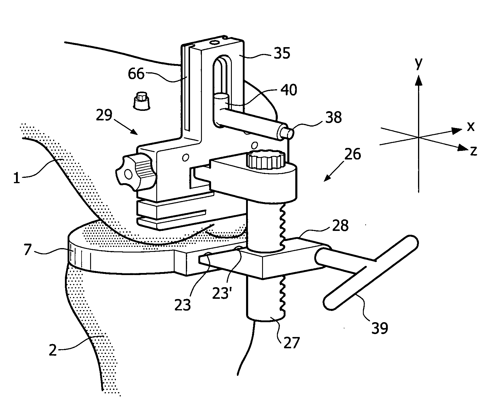
Devices and method for performing replacement prosthetic knee surgery are disclosed in which a spacing means is introduced between the femur (1) and tibia (2) while the patella (9) is in place. The spacing means separates the femur (1) from the tibia (2) by an amount essentially equal to or greater than the required flexion gap (4). An alignment device (26) is used for performing femoral bone cuts, which device attaches temporarily to a fitted tibial plate.

Description

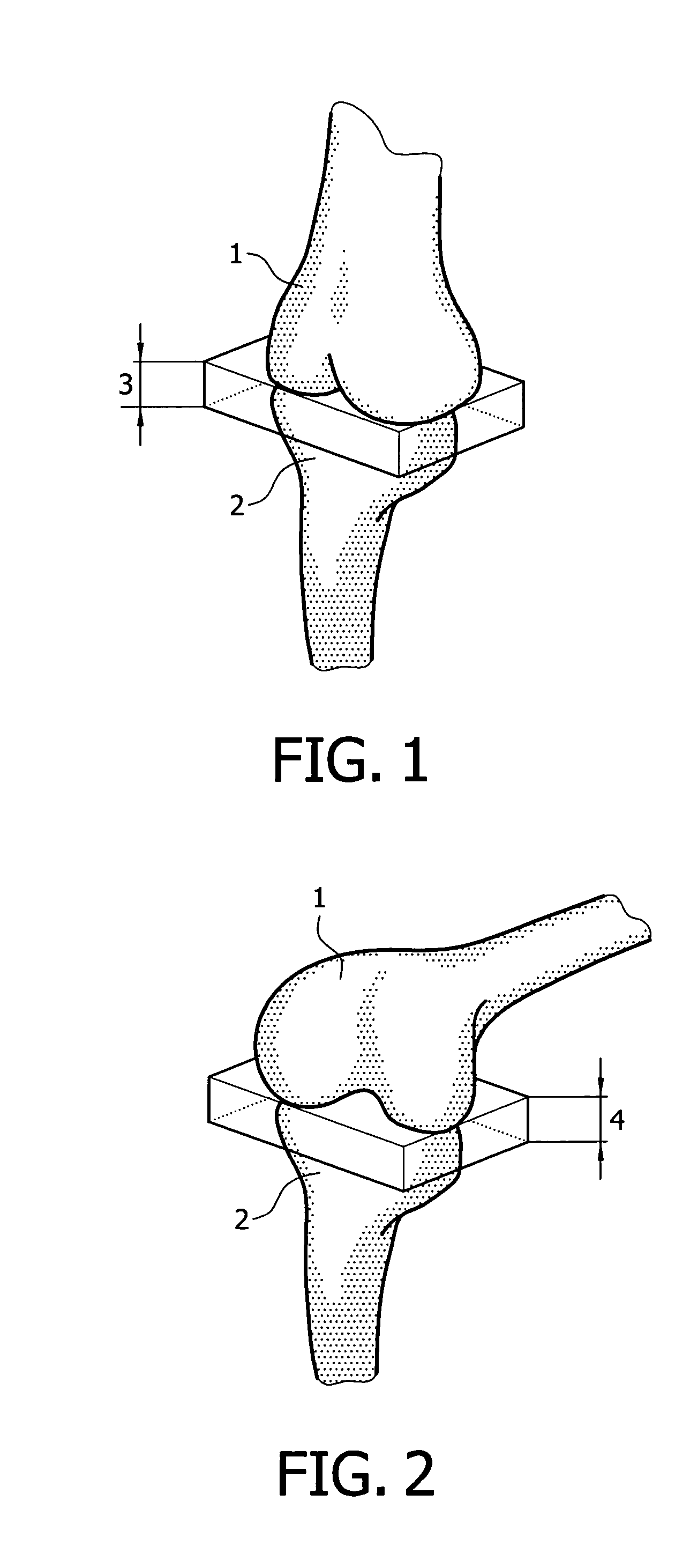
[0001]During surgery for fitting a prosthetic knee joint, a number of bone cuts are made to allow placement and orientation of the femoral component of the prosthesis, and to determine and form the joint gaps in extension and flexion 4 (see FIG. 1). The size and shape of these two gaps affect final orientation of the prosthesis, as well as joint tensioning and clearances.[0002]Generally, the bone cuts are formed so that in extension the joint gap is perpendicular to the mechanical axis of the femur, while in flexion the joint gap is such as to place the femoral component in either neutral or external rotation and assure proper patellar tracking with the femoral component. To fit the femoral component the gaps created by the bone resections in both flexion and extension should be of dimensions to achieve the previous tension in between femur and tibia in flexion after the prosthesis is fitted. Therefore, the cuts must account for the thickness of the femoral and tibial prostheses, an...

Claims


Application Information

Patent Timeline
Patent Type & Authority Applications(United States)
IPC IPC(8): A61B17/56
CPCA61B17/025A61B17/155A61B2017/00407A61B17/1764A61F2/38A61F2/461A61B17/1725A61B2017/0268
Inventor GHIJSELINGS, IGNACE
Owner GHIJSELINGS IGNACE
Learn More