Mr method and apparatus for determining coronal and sagittal image planes from an image data set of a knee joint

a technology of image data and knee joint, applied in image analysis, instruments, computing, etc., can solve problems such as difficulty, pain in the knee joint region, and impair the patient's freedom of movement,

Inactive Publication Date: 2010-04-06
SIEMENS HEALTHCARE GMBH
View PDF3 Cites 40 Cited by
  • Summary
  • Abstract
  • Description
  • Claims
  • Application Information

AI Technical Summary

Benefits of technology

[0013]In an embodiment of the invention, a center point in which the coronal and the sagittal planes are shifted is determined for a subsequent slice image acquisition after the determination of the coronal or the sagittal plane using at least one analysis algorithm. From this center point, a circle (approximating the shape of a transverse slice of the femoral bone head) around the femoral bone head and its middle point is determined. The middle point is the central point in which both planes that serve as central planes for the subsequently-acquired plane-parallel slice images are placed. This embodiment of the invention enables a coronal plane and a sagittal plane to be defined as a center plane for the acquisition of subsequent planes of parallel slice image families. A previously-determined coronal or sagittal plane is inventively shifted in a plane-parallel manner into the middle of the femoral bone head (likewise serving as an anatomical landmark) that is determined by an analysis algorithm. This plane forms the central plane for the later slice images that are subsequently acquired in a plane-parallel manner on both sides thereof. The determination of the center of the femoral bone head is likewise possible without anything further using the analysis algorithm because the bone is essentially visible horseshoe-shape in the transversal slice image. A circular line whose position and radius are oriented on the shape or contour of the bone section is approximated to this as closely as possible is now automatically determined using the contours of the bone section. At this circle, the middle point that forms the center point into which the planes are shifted is now determined by the analysis algorithm. This embodiment of the invention thus enables an automatic central plane determination. Alternatively, starting from the determination of both coronal and sagittal orientation planes, the diagnosing physician can determine in which direction the examination volume should be acquired, starting from both of these orientation planes.

Problems solved by technology

Diseases in the region of the knee joint are painful and impair the patient in terms of freedom of movement.
Difficulties arise, however, when a follow-up examination is to ensue at a later point in time in order to implement therapy monitoring.
Because the individual slice image groups, or the various measurement protocols (for example T1 or T2), typically are set manually in coronal, sagittal and transversal orientation by the apparatus operator (technician), difficulties occur with regard to reproducing the original slice plane positioning.
This applies even when the same operator does the setting at a later point in time, but is particularly a problem when a different operator acquires the later data.
The slice images previously acquired do not normally exist as references, such that the later technician cannot make use of them for orientation purposes.
Similar problems also occur when acquired slice images are to be evaluated at a later point in time.
Again, no reproducibility is achieved.

Method used


Image

  • Mr method and apparatus for determining coronal and sagittal image planes from an image data set of a knee joint
  • Mr method and apparatus for determining coronal and sagittal image planes from an image data set of a knee joint
  • Mr method and apparatus for determining coronal and sagittal image planes from an image data set of a knee joint

Examples


Embodiment Construction

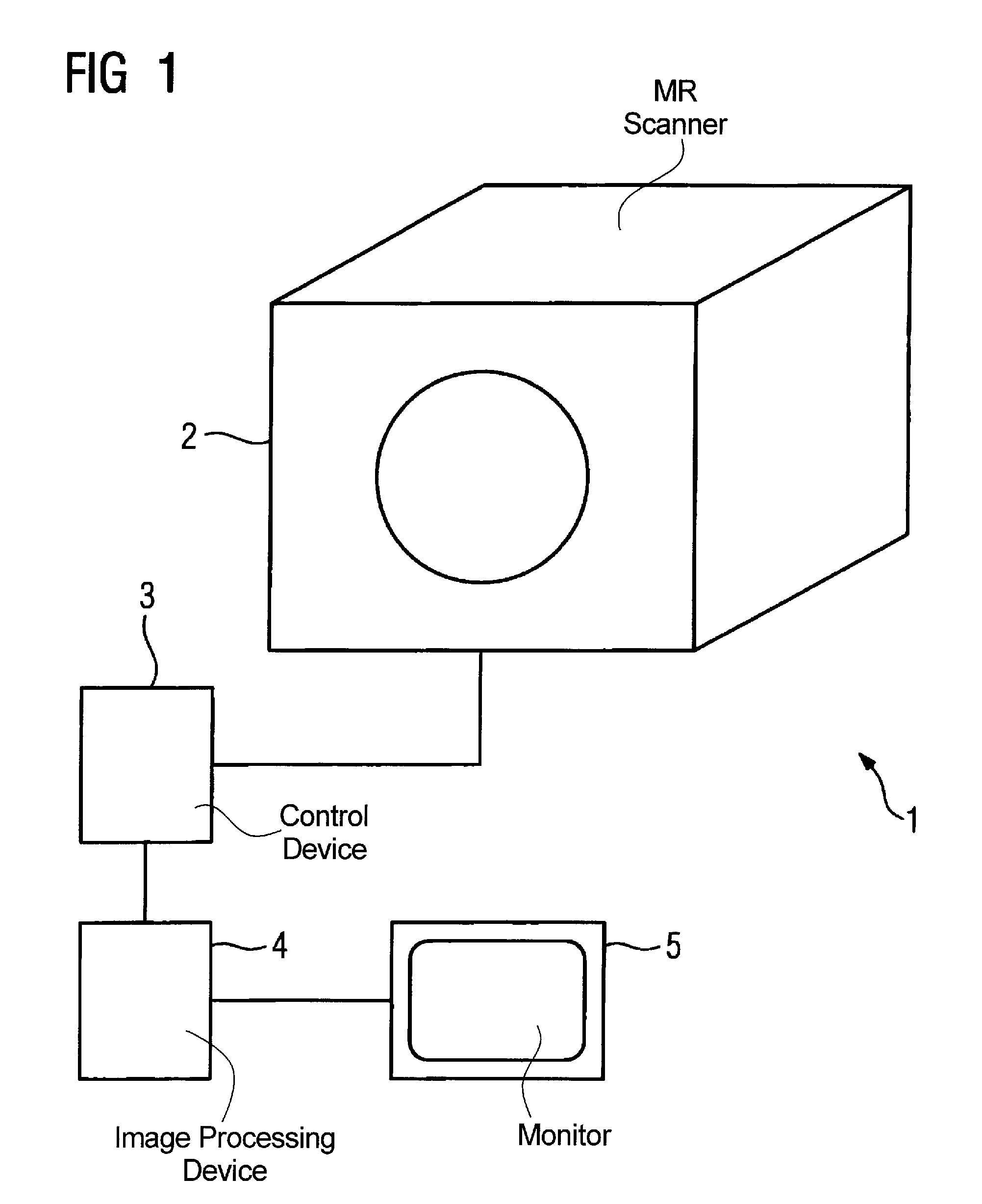
[0019]FIG. 1 shows an inventive magnetic resonance system 1 that has an MR scanner 2 connected to a control device 3 (controlling the operation) with an associated image processing device 4 that includes a suitably fashioned or programmed calculation device. The control device 3 controls the entire operation flow, including the image acquisition; the image processing ensues in the image processing device 4, with which a monitor 5 is connected for image display.

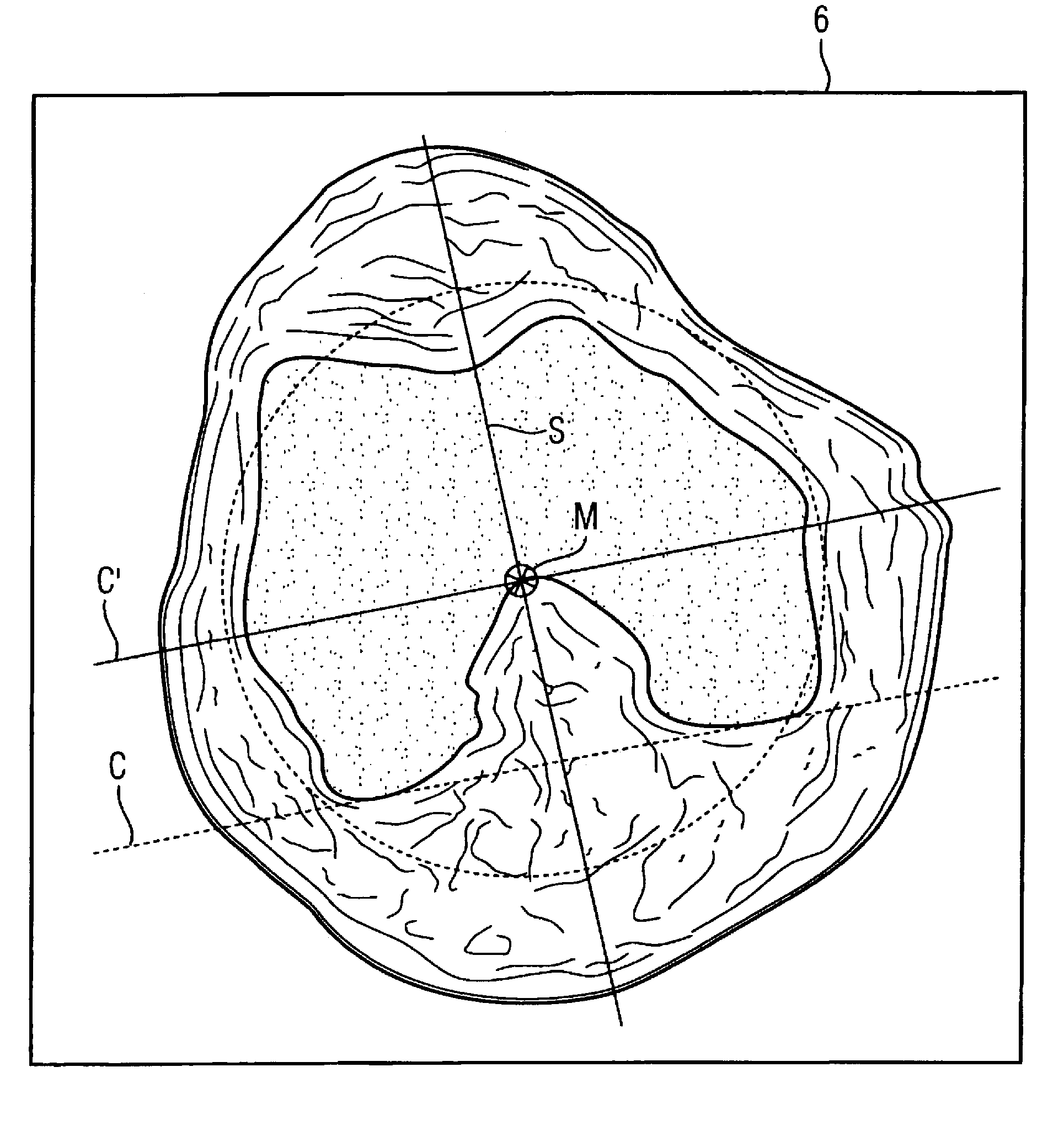
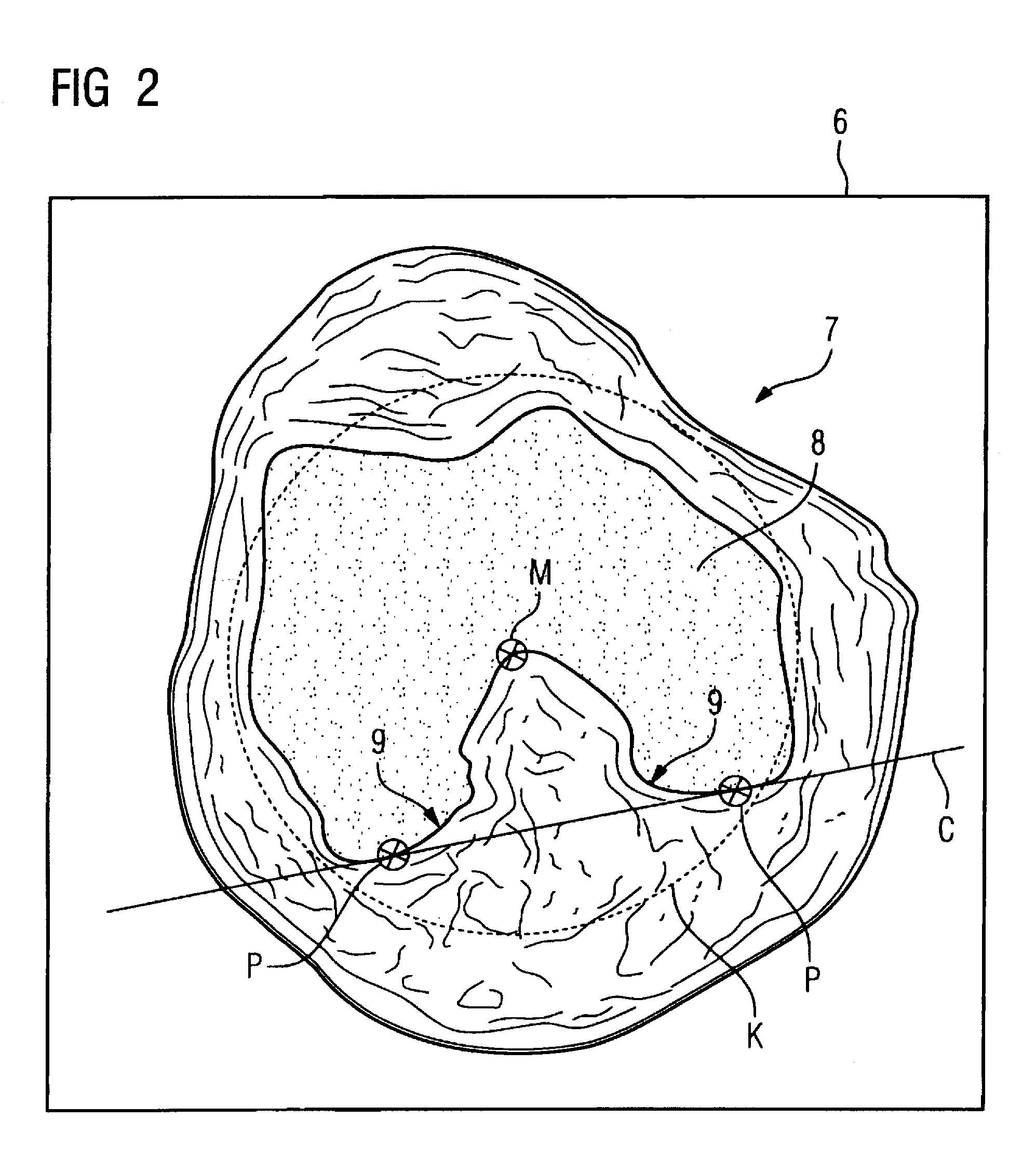
[0020]For a knee joint examination, three localizer exposures, (overview images), are initially acquired as is typical in three defined orthogonal orientations of the knee joint region, the localizer exposures serving for the generation of a rough overview image. A transversal plane that proceeds through the knee joint is now automatically determined using these localizer exposures. A first transversal slice image family is now automatically acquired based on this automatically-determined alignment of the transversal plane. Th...


PUM


Abstract

In a method for determination of coronal and sagittal planes for the subsequent acquisition of new magnetic resonance slice images or the representation of magnetic resonance slice images from an existing image data set of a knee joint, starting from a data set representing a transversal slice image of the knee joint, the slice image is analyzed using at least one analysis algorithm to identify the medial and the lateral condyles of the femoral bone head shown as a transversal section and a point lying thereon in a section that defines a coronal plane that is tangential to the condyles. The sagittal plane proceeding perpendicular to the defined coronal plane is then determined. Coronal or sagittal slice images are then acquired or represented with orientations dependent on the identified planes.

Description

BACKGROUND OF THE INVENTION[0001]1. Field of the Invention[0002]The present invention concerns a method for determining of distinguished coronal and sagittal planes from an already-present image data set of a knee joint for the subsequent acquisition of new magnetic resonance slice images or the representation of magnetic resonance slice images.[0003]2. Description of the Prior Art[0004]Diseases in the region of the knee joint are painful and impair the patient in terms of freedom of movement. Magnetic resonance tomography is a gentle method for examination of the knee joint. In order to acquire an optimally large amount of information from the examination region, so as to be able to generate meaningful slice image therefrom, the shoulder joint is acquired in the form of a number of slice image sets that are respectively acquired in specific planes. The data acquisition ensues in the transversal, coronal and sagittal directions, but these planes need not be exactly perpendicular to ...

Claims


Application Information

Patent Timeline
Patent Type & Authority Patents(United States)
IPC IPC(8): G06K9/00
CPCG06T7/0012
Inventor LEHTONEN-KRAUSE, SARI
Owner SIEMENS HEALTHCARE GMBH
Why Eureka
Try Eureka