Eureka AIR delivers breakthrough ideas for toughest innovation challenges, trusted by R&D personnel around the world.

Booster valve

Active Publication Date: 2010-09-30
SUBARU TECNICA INTERNATIONAL
View PDF33 Cites 7 Cited by
  • Summary
  • Abstract
  • Description
  • Claims
  • Application Information

AI Technical Summary

Problems solved by technology

In addition, large scale applications may utilize large volume actuators to react to the high forces that are typical of severe service control valves.
When a large volume actuator is utilized in the pneumatic circuit of the actuation system, the positioner, acting alone, may be unable to supply and exhaust a sufficient volume of compressed air to the actuator within a given time period.
As a result, such pneumatic circuits having large volume actuators may be incapable of achieving a quick stroking speed of the piston.
However, where a low flow rate positioner is utilized, pneumatic circuits operating with large volume actuators may not be able to energize the boosters.
Consequently, they suffer the drawback of a slow stroking speed.
However, the benefits to the actuation system that are provided by the addition of the first and second boosters are often accompanied by a performance penalty in the pneumatic circuit of the actuation system.
More particularly, the increased number of active components in the pneumatic circuit often gives rise to dynamic instability wherein the piston is difficult to precisely and rapidly position.
Thus, there may be an undesirable lag time between the time that the positioner receives the piston position signal and the time that the piston arrives at the desired position.
Also, the piston may overshoot the final position, with overshooting occurring when the piston, moving at a relatively high rate of speed, fails to slow down as it nears the final position such that it moves past the desired position and then must reverse directions.
The overshooting of the piston therefore increases the overall lag time of the actuator.

Method used


Image

  • Booster valve
  • Booster valve
  • Booster valve

Examples


Embodiment Construction

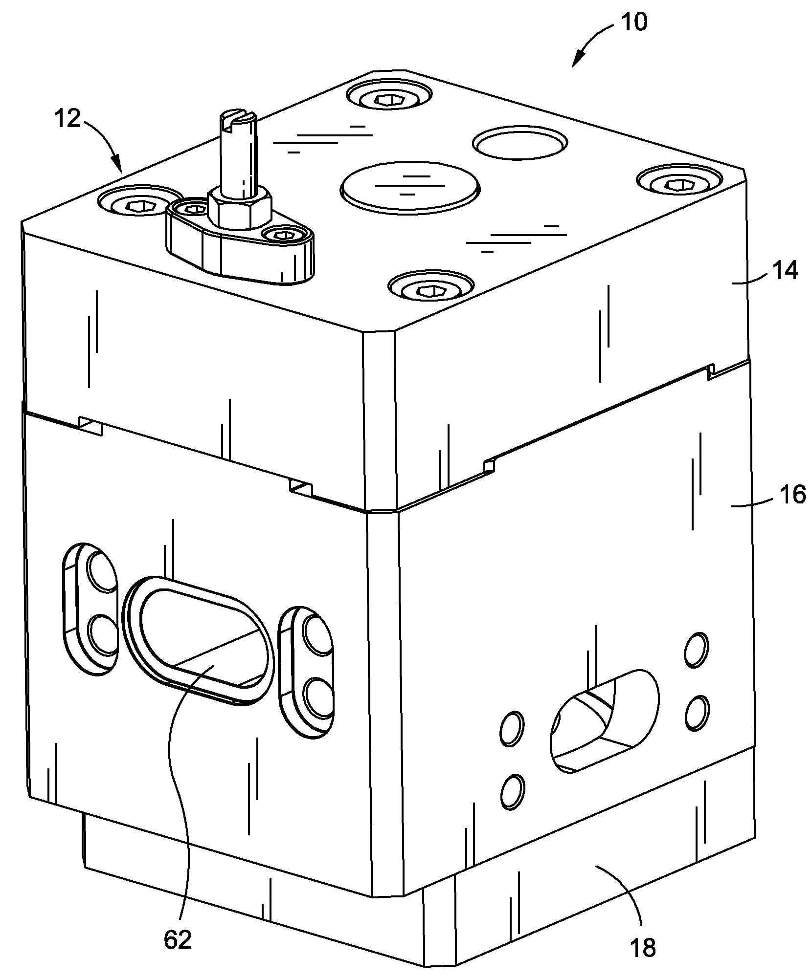
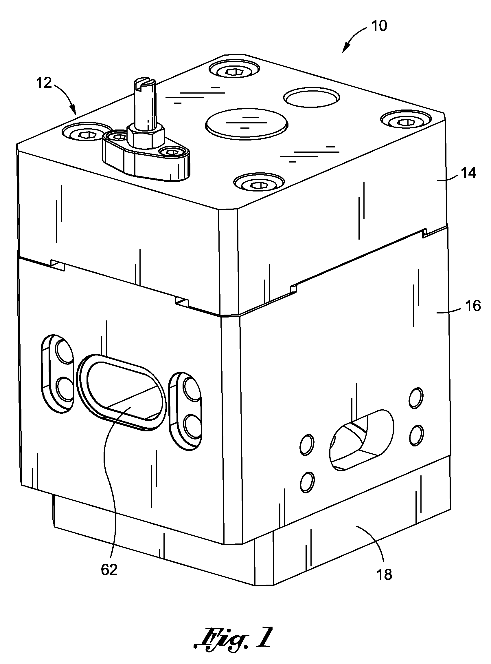
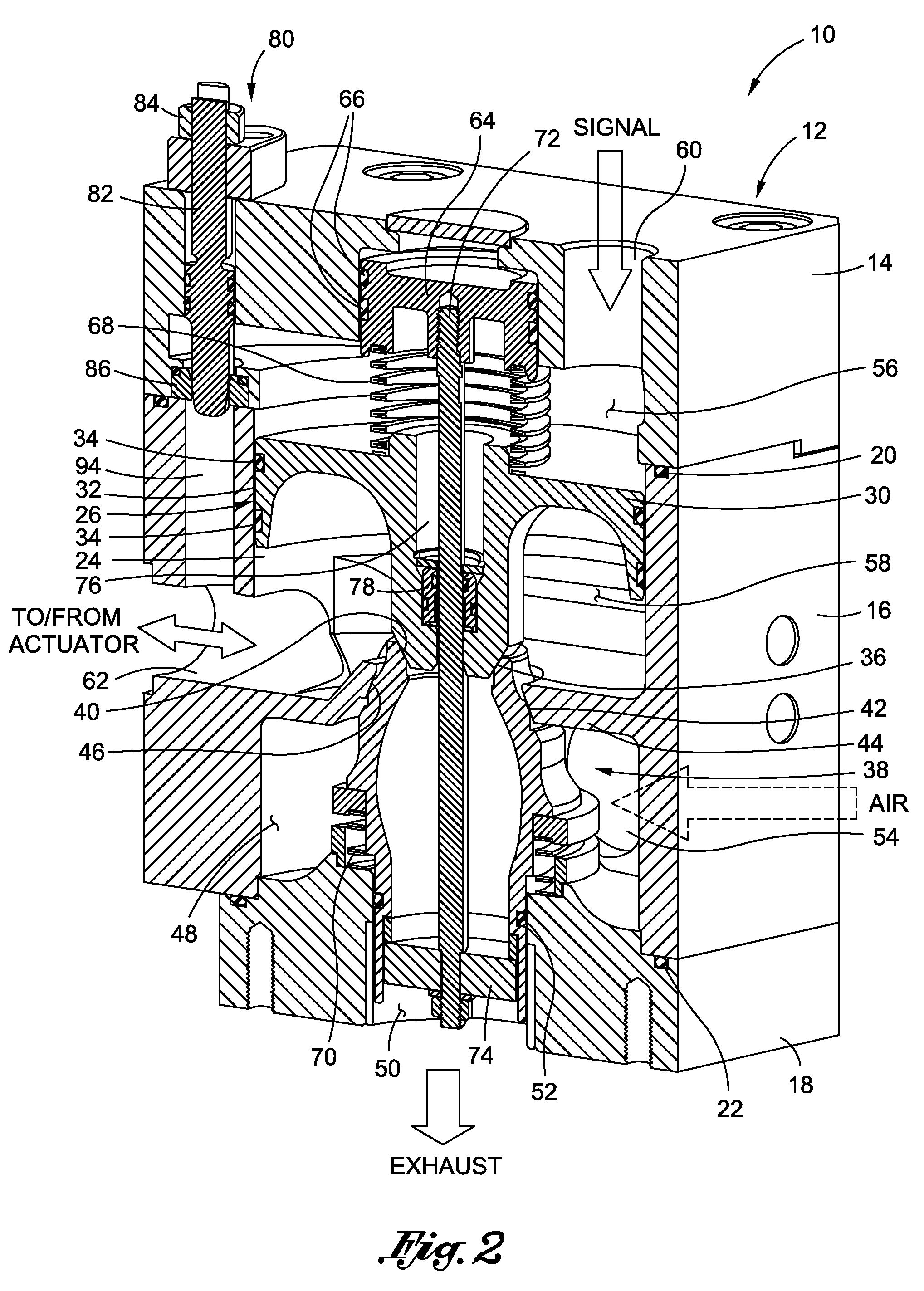
[0022]Referring now to the drawings wherein the showings are for purposes of illustrating a preferred embodiment of the present invention only, and not for purposes of limiting the same, FIG. 1 perspectively illustrates a booster valve 10 constructed in accordance with the present invention. In FIG. 2, the booster valve 10 is depicted in a neutral, no pressure position. In FIG. 3, the booster valve 10 is depicted in a delivery position, while in FIG. 5, the booster valve 10 is depicted in a discharge position. The structural and functional attributes of the booster valve 10 when in the neutral, delivery and discharge positions will be described in more detail below.

[0023]The booster valve 10 comprises a housing 12 which has a generally cubic configuration. As viewed from the perspective shown in FIGS. 2, 3 and 5, the housing 12 includes a first (upper) section 14, a second (middle) section 16, and a third (lower) section 18. The second section 16 is effectively captured between the ...


PUM


Abstract

A booster valve comprising a housing having a signal port, an actuator port, a supply port, and an exhaust port disposed therein. Disposed within the housing are upper and lower plugs. The upper and lower plugs and the housing collectively define a signal chamber which fluidly communicates with the signal port, an actuator chamber which fluidly communicates with the actuator port, and a supply chamber which fluidly communicates with the supply port. The upper and lower plugs are selectively moveable between neutral, delivery and discharge positions. When in the neutral position, the actuator chamber is fluidly isolated from both the supply chamber and the exhaust port. When in the delivery position, the actuator chamber fluidly communicates with the supply chamber but is fluidly isolated from the exhaust port. Finally, when in the discharge position, the actuator chamber fluidly communicates with the exhaust port but is fluidly isolated from the supply chamber.

Description

CROSS-REFERENCE TO RELATED APPLICATIONS[0001]Not ApplicableSTATEMENT RE: FEDERALLY SPONSORED RESEARCH / DEVELOPMENT[0002]Not ApplicableBACKGROUND OF THE INVENTION[0003]1. Field of the Invention[0004]The present invention relates generally to fluid flow control devices and, more particularly, to a uniquely configured booster valve for integration into a pneumatic circuit of a valve actuation system.[0005]2. Description of the Related Art[0006]Pneumatic valve actuation systems typically comprise a source of compressed air that is routed through a network of fluid conduits such as pipes. The compressed air is typically provided by an air compressor. The compressed air is routed to a positioner that ultimately controls the flow of compressed air into and out of an actuator. More particularly, the positioner provides a metered flow of compressed air into alternate ends of the actuator in response to a positioner input signal. The actuator may be, for example, a double acting actuator compr...

Claims


Application Information

Patent Timeline
IPC IPC(8): F16K31/122
CPCF15B13/042F16K31/1223F16K31/1221F16K11/048Y10T137/87225Y10T137/87241
Inventor TONDOLO, FLAVIO
Owner SUBARU TECNICA INTERNATIONAL
Why Eureka
Eureka Blog
Learn More