Luminance control method and display

a technology of display device and control method, which is applied in the field of control of the brightness (luminance) of the backlight of the display device, can solve the problem of difficult to see the screen in extremely bright conditions, and achieve the effect of improving the power of expression on the screen

Inactive Publication Date: 2010-09-30
NEC CORP
View PDF7 Cites 23 Cited by
  • Summary
  • Abstract
  • Description
  • Claims
  • Application Information

AI Technical Summary

Benefits of technology

[0011]According to the present invention, it is possible to achieve convenience for users as well as improving the power of expression on the screen in controlling the brightness of the backlight.

Problems solved by technology

On the other hand, even if the screen becomes bright after the backlight is switched on, it may be difficult to see the screen in extremely bright conditions such as areas around lighting equipment or under clear skies.

Method used


Image

  • Luminance control method and display
  • Luminance control method and display
  • Luminance control method and display

Examples


Embodiment Construction

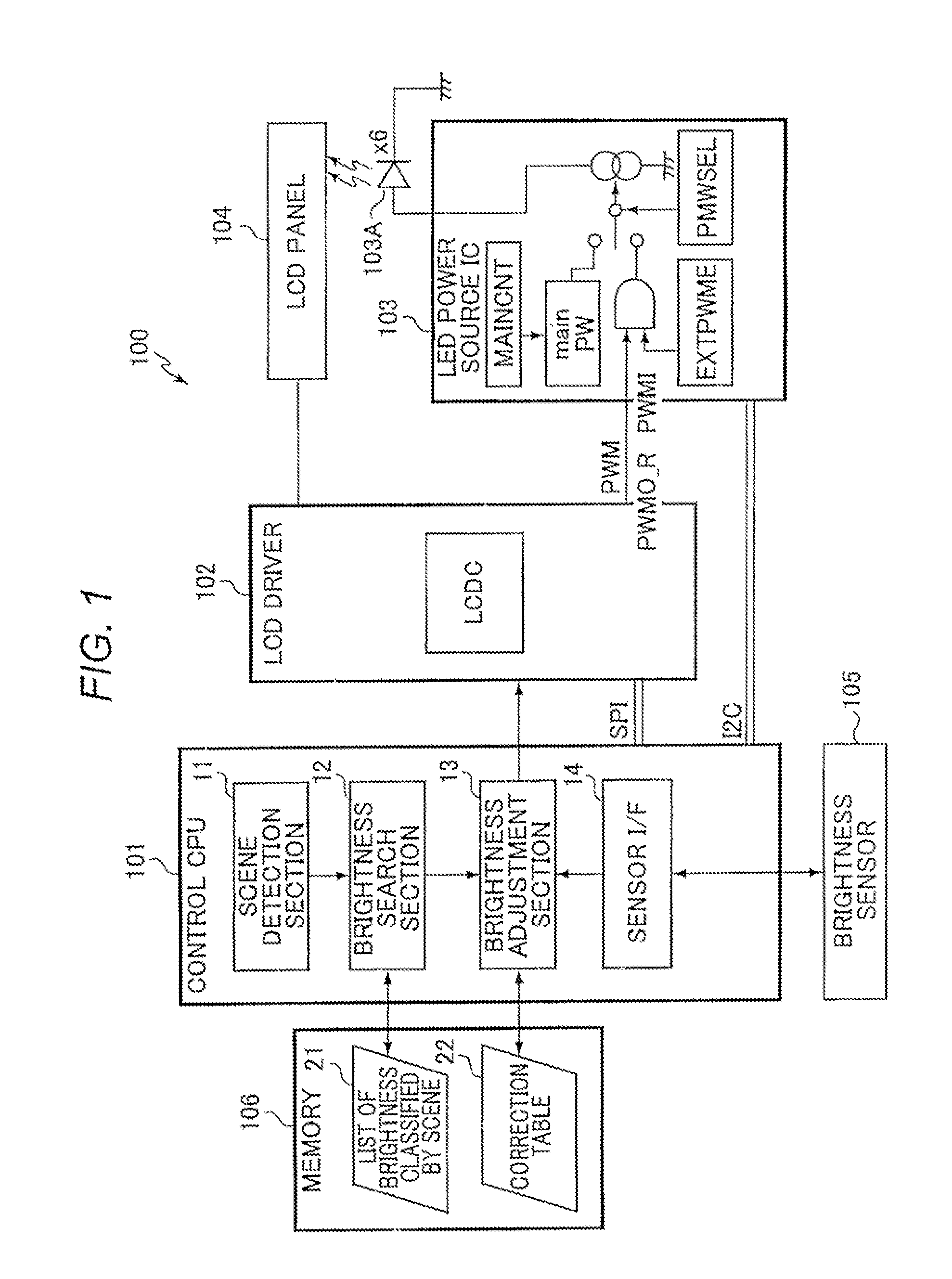
[0030]FIG. 1 shows the configuration of a display device according to an embodiment of the present invention. According to the present embodiment, a display device 100 is expected to be incorporated into a portable terminal (not shown in the diagram) such as a cellular phone. As shown in FIG. 1, the display device 100 includes a control CPU 101, a LCD driver 102, a LED 103A, a LED power source IC 103, a LCD panel 104, a brightness sensor 105, and a nonvolatile memory 106. {0014} The LED 103A and the LED power source IC 103 correspond to a light emitting device of the present invention. The control CPU 101 corresponds to a control device of the present invention. The control CPU 101 controls the brightness of a backlight as well as the operations of the terminal such as communication and data processing.

[0031]The control CPU 101 uses SPI (Serial Peripheral Interface) to transmit drawing data and various kinds of instruction to the LCD driver 102 and controls the LED power source IC 1...


PUM


Abstract

A display device includes a display panel, a light emitting device that provides backlight to the display panel, and a control device that determines the brightness of the backlight that the light emitting device should provide. The control device detects a timing when the brightness of the backlight illuminating the display panel is switched; recognizes an updated brightness level that should replace, as the one to be applied, an initial brightness level representing the brightness of the backlight at the detection timing; and changes the brightness of the backlight step by step after the detection timing from the initial brightness level to the updated brightness level.

Description

TECHNICAL FIELD[0001]The present invention relates to a technique of controlling the brightness (luminance) of a backlight of a display device.BACKGROUND ART[0002]Regarding a portable terminal such as cellular phone, for example, when the case of a folding type is flipped open or when a user operates a terminal, a backlight of LCD (Liquid Crystal Display) is automatically switched on and the screen becomes bright. Moreover, as a measure for reducing power consumption in terminals, there is a well-known function of automatically turning off the backlight after a predetermined period of time has passed without any operation.[0003]A predetermined level of brightness is set in the backlight of the terminal screen for each of operating scenes of the terminal such as executed applications and occurrence of events. Therefore, the screen switches to a different level of brightness depending on operating scene. For example, the reason the screen becomes bright when the case is opened is that...

Claims


Application Information

Patent Timeline
Patent Type & Authority Applications(United States)
IPC IPC(8): G09G5/10
CPCG09G3/3406G09G2320/06G09G2320/0633H04M2250/12G09G2360/144H04M1/22G09G2320/0653
Inventor HASHIMOTO, MASAHIRO
Owner NEC CORP
Why Eureka
Try Eureka