
Printing apparatus, printing method and image processor

a printing apparatus and printing method technology, applied in the field of printing apparatus and printing method, can solve the problems of density unevenness, reduced grayscale level in the unit area, perceived density unevenness, etc., and achieve the effect of reducing density unevenness and no density unevenness

Active Publication Date: 2010-09-30
CANON KK
View PDF14 Cites 9 Cited by
  • Summary
  • Abstract
  • Description
  • Claims
  • Application Information

AI Technical Summary

Benefits of technology

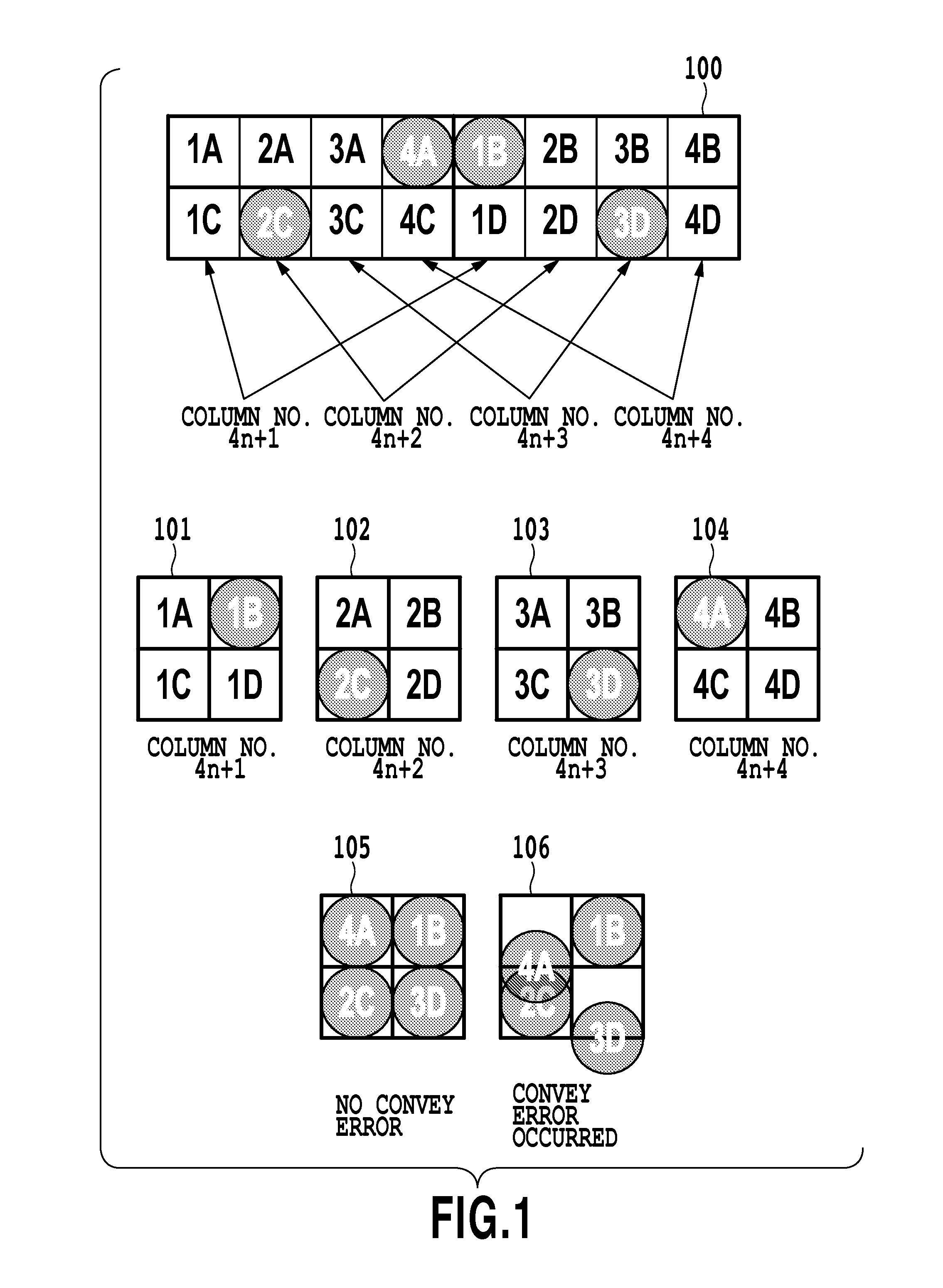
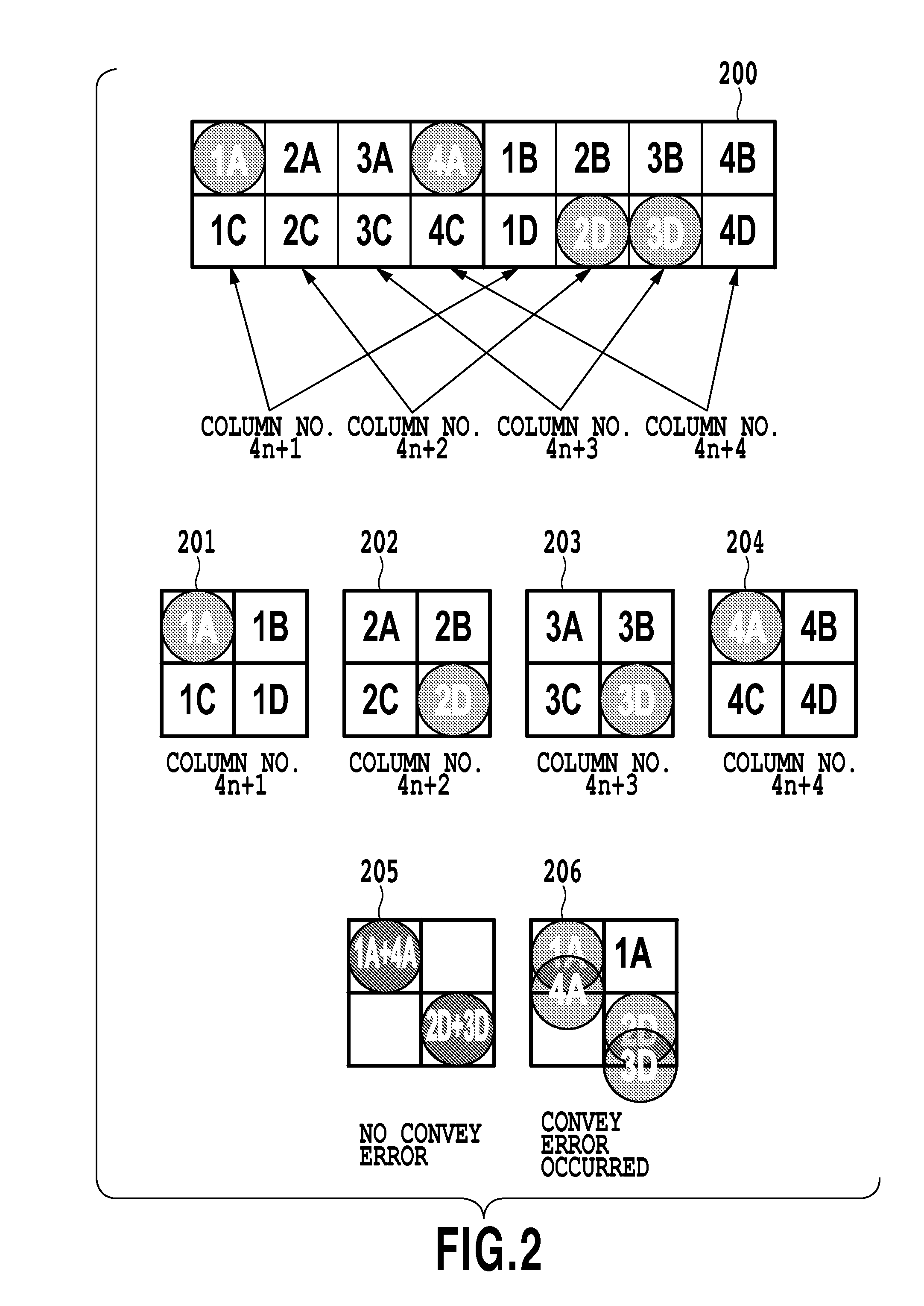
The present invention provides a printing apparatus and method that can minimize variations in density among unit areas and produce an image with no density unevenness even if print position misalignments occur unexpectedly during a multipass printing process. The invention achieves this by converting image data for a grayscale expression in one pixel into print data determining each of a plurality of subpixels making up the one pixel either to be printed or not to be printed with dot according to a plurality of dot arrangement patterns that determine each of the plurality of subpixels making up the one pixel either as a subpixel to be printed or as a subpixel not to be printed. The dot arrangement patterns are constructed such that the ratio of the number of subpixels determined to be printed with plural dot to the number of subpixels determined to be printed with one or more dots (overlapping ratio) increase and the ratio of the number of subpixels determined to be printed adjoining one subpixel in focus to the number of subpixels determined to be printed adjoining the subpixel in focus is larger than 0% and lower than 100%.

Problems solved by technology

These variations may result in a density unevenness and stripes showing up in a printed image.
In recent years, however, density changes or grayscale level changes caused by a print position misalignment (misregistration) among different print scans during the above multipass printing have come to be viewed as a new issue.
As a result, a complementary relationship among the dots collapses, lowering a dot coverage over the print medium (or area factor), which in turn reduces a grayscale level in the unit area.
Further, if unit areas with such print position misalignments and those with no such misalignments are intermingled on the same print medium, the above phenomenon is perceived as a density unevenness.
So, if a print position misalignment occurs among different dot groups, as caused by unexpected shifts during convey operations, the dot dispersion is greatly lost, making image impairments brought about by density reductions easily noticeable.
That is, in an image that has a large proportion of print data in other than the overlapping subpixels, the method cannot produce its intended effect.
As described above, not one conventional technique can avoid the problem of density variations in the event of a print position misalignment caused by unexpected shifts during print medium convey operations or the like.

Method used


Image

  • Printing apparatus, printing method and image processor
  • Printing apparatus, printing method and image processor
  • Printing apparatus, printing method and image processor

Examples


first embodiment

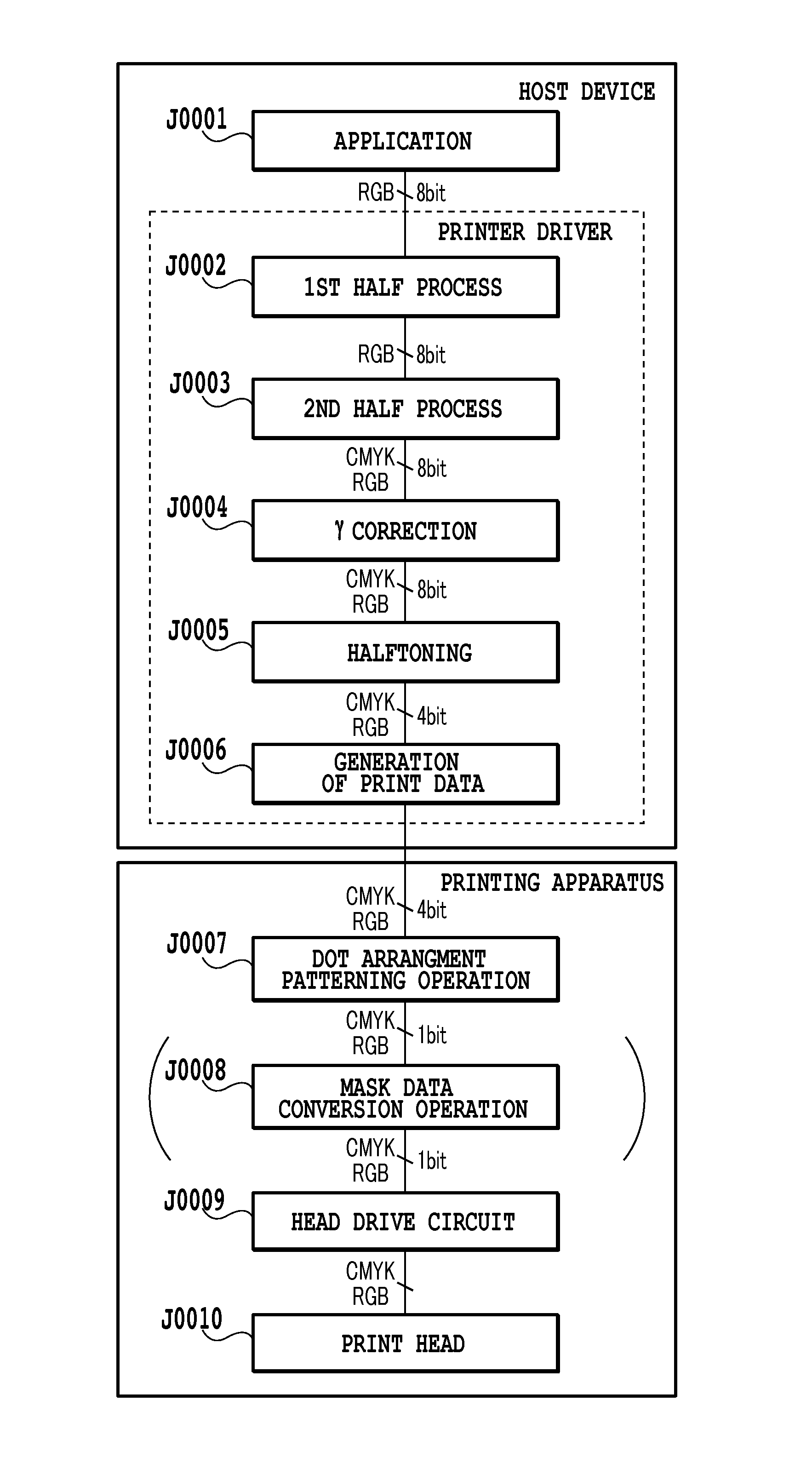
[0063]A first embodiment of this embodiment will be described in detail in the following. First, a construction of a body of an inkjet printing apparatus applied to this embodiment will be explained.

(Construction of Mechanical Section)

[0064]The printing apparatus body in this embodiment may be classed in terms of function into a feeder section, a print medium conveying section, a discharging section, a carriage section, a cleaning section and an enclosure. Outlines of these will be explained as follows.

(A) Paper Feed Unit

[0065]FIGS. 19 and 20 are perspective views showing a printing apparatus applied to this embodiment, with FIG. 19 representing a state of the printing apparatus M1 when not in use and FIG. 20 a state of the printing apparatus M1 when in use. FIGS. 21, 22 and 23 show an internal mechanism in the printing apparatus body, with FIG. 21 representing a perspective view as seen from right above, FIG. 22 representing a perspective view as seen from left above and FIG. 23 re...


PUM


Abstract

A printing apparatus and a printing method are provided which, even if a print position misalignment occurs between a plurality of print scans during a multipass printing, can minimize density variations in a unit area reliably and stably, thus producing an image without density unevenness. For this purpose, multi-grayscale-level image data is converted into a plurality of dot arrangement patterns that determine individual subpixels either to be printed or not to be printed with a dot. Then, these dot arrangement patterns are printed overlappingly on a print medium in different print scans of the print head. At this time, the plurality of dot arrangement patterns are so arranged that, if these dot arrangement patterns are shifted from one another, a change in the dot-overlapping area ratio will be smaller than when the dots are arranged separately so that they do not overlap one another.

Description

BACKGROUND OF THE INVENTION[0001]1. Field of the Invention[0002]The present invention relates to a printing apparatus and a printing method that cause a print head having ink-ejecting nozzles to print on a print medium as it scans over the print medium.[0003]2. Description of the Related Art[0004]Inkjet printing apparatus of serial type uses a print head having a plurality of ink-ejecting printing elements (or nozzles) and performs a printing operation by repetitively alternating a print scan and a print medium convey operation, the print scan causing the print head to eject ink as it moves over the print medium. Among a plurality of nozzles there are some unavoidable variations in an ink ejection volume and in an ejection direction. These variations may result in a density unevenness and stripes showing up in a printed image. To alleviate these density unevenness and stripes, a multipass printing method such as disclosed in Japanese Patent Laid-Open No. H05-31922 (1993) has been kn...

Claims


Application Information

Patent Timeline
Patent Type & Authority Applications(United States)
IPC IPC(8): B41J2/205
CPCG06K15/107
Inventor KANO, YUTAKANISHIKORI, HITOSHIKAWATOKO, NORIHIROKONNO, YUJIISHIKAWA, TOMOKAZUYAMADA, AKITOSHIONO, MITSUHIROKAJIHARA, RIE
Owner CANON KK
Learn More