
Printer

Inactive Publication Date: 2010-09-30
CANON KK
View PDF34 Cites 10 Cited by
  • Summary
  • Abstract
  • Description
  • Claims
  • Application Information

AI Technical Summary

Benefits of technology

[0009]A main object of the present invention is to further improve the conventional printer. A further object of the present invention is to provide a compact lightweight printer having its cost limited and capable of performing recording with high accuracy.

Problems solved by technology

Further, in some case, because the discharge roller and the platen are positioned by being fitted to the chassis, the back tension applied to the sheet varies due to small fluctuations of the platen and the discharge roller during sheet transport, resulting in a deterioration in paper feed accuracy.
Also, if the above-described fitting positioning is employed, because positioning errors are added to the amounts of variation in height of the discharge roller and the platen, there is an anxiety about a deterioration in paper feed accuracy due to variation in the back tension and a deterioration in paper feed accuracy when the sheet leading end runs onto the nip line between the discharge roller and spurs.

Method used


Image

  • Printer
  • Printer
  • Printer

Examples


first embodiment

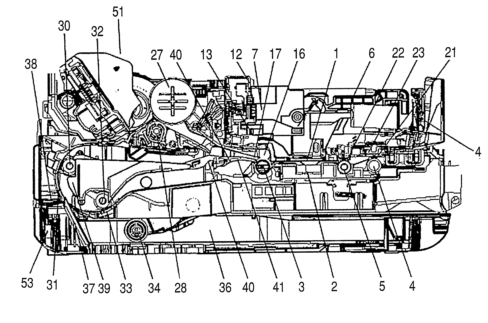
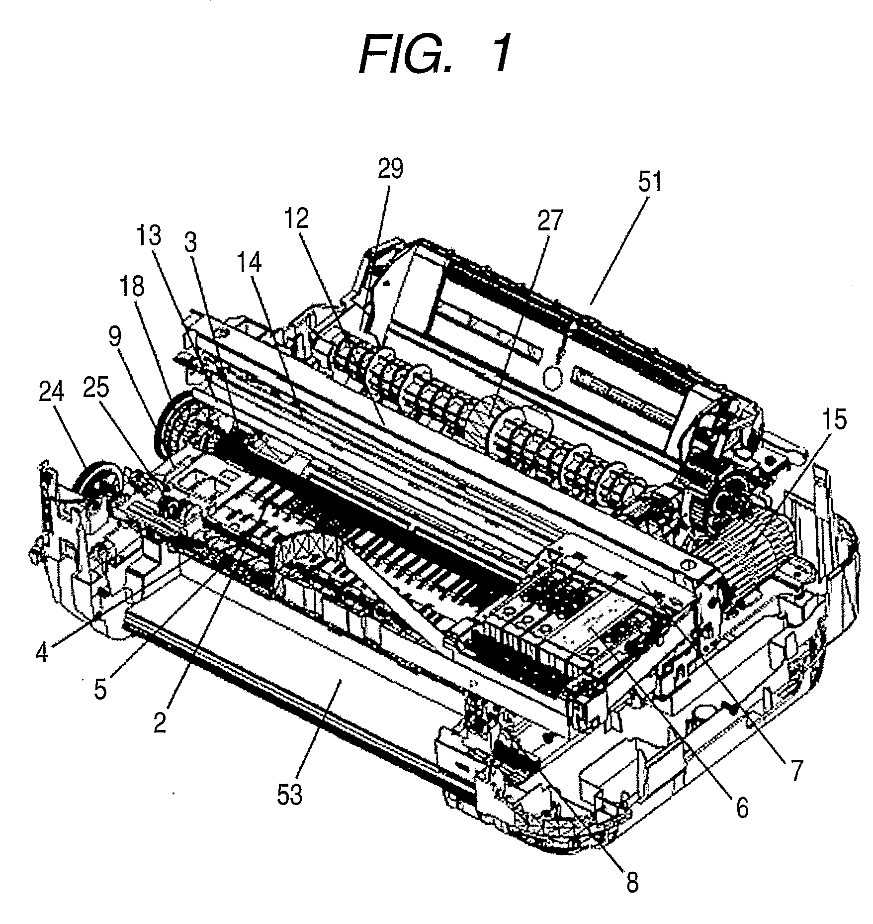
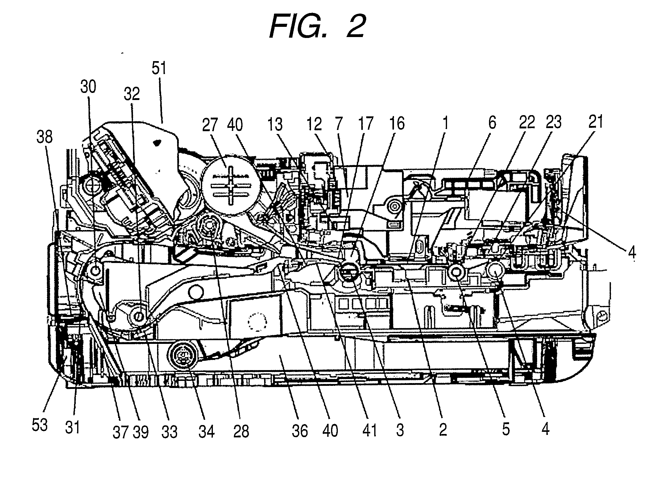
[0036]A first embodiment of the present invention will be described with reference to FIGS. 1, 2, 3, 4, 5, 6, 7, 8, 9, 10 and 11. The entire construction of the main body of an apparatus in the first embodiment will be described with reference to FIGS. 1, 2, 3 and 4. FIG. 1 is a perspective view illustrating constituent sections in the first embodiment. FIG. 2 is a sectional view of the main body. FIGS. 3 and 4 are perspective view illustrating the entire main body.

[0037]Sheets are stacked in a feed unit 51, separated and fed one after another by a nip between a feed roller 27 and a separating roller 28 and transported to a transport roller 3. The transport roller 3 is disposed on the upstream side of a printing head 1 in the sheet transport direction to transport sheets to a printing section. A pinch roller 16 is urged against the transport roller 3 by spring members to apply a transport force to the recording sheet while rotating in a following manner. The pinch roller 16 is held ...

second embodiment

[0057]A second embodiment will be described with reference to FIGS. 10 and 11. The construction is such that a both-side recording construction is added to the first embodiment. The both-side transport roller 32 is positioned and held on the right side member 8 and the left side member 9 by being brought into direct contact with the same or by means of bearing members. The outer U-turn guide 38 and the inner U-turn guide 39 are also positioned and held on the right side member 8 and the left side member 9 in the same manner as the transport roller sheet guide 40 and the sheet guide flapper 41.

third embodiment

[0058]A third embodiment will be described with reference to FIG. 12. The construction is such that a front chassis 42 is added to the first embodiment. The front chassis 42 is positioned on the right side member 8 and the left side member 9 and is fixed with connecting members such as small screws, in the same manner as the carriage chassis 12.


PUM


Abstract

A printer has a pair of a right side member (8) and a left side member (9) placed on opposite side portions of a base (53), rollers including a transport roller (3), a carriage chassis (12), a platen (2) and a feed unit. The right side member and the left side member are formed by molding a resin material. The roller, the carriage chassis, the platen and the feed unit are positioned and held with the pair of the right side member and the left side member.

Description

TECHNICAL FIELD[0001]The present invention relates to a printer which forms an image on a sheet with a printing head.BACKGROUND ART[0002]The construction of a main body of a conventional ink jet printer will be described. For conventional printers, a divided chassis construction using a metalwork material has been adopted. On chassis members in the divided chassis construction, constituent members relating to recording are positioned and held.[0003]The construction of a printer disclosed in U.S. Patent Publication No. 2006 / 0024118 will be described by way of example with reference to FIG. 23. A multiple feed unit section (not shown) 10 having a plurality of feed sections and a both-side transport section is fixed in a state of being interposed between a right chassis 112 and a left chassis 113. The right chassis 112 and the left chassis 113 are formed of a metalwork material or the like having a certain strength. A main chassis 11 formed of a metalwork material is provided on the fr...

Claims


Application Information

Patent Timeline
IPC IPC(8): B41J2/01
CPCB41J29/02B41J29/13B41J11/02B41J11/04
Inventor UCHIDA, HARUOIKEDA, YASUHIKOSAITO, HIROYUKISHIGENO, KENJIKAWAGUCHI, KOICHIROISHIDA, TAKAAKI
Owner CANON KK
Features
  • Generate Ideas
  • Intellectual Property
  • Life Sciences
  • Materials
  • Tech Scout
  • Unparalleled Data Quality
  • Higher Quality Content
  • 60% Fewer Hallucinations
Learn More