Directional valve and respirator product with a directional valve

Active Publication Date: 2014-03-20
DRAGER SAFETY
View PDF1 Cites 10 Cited by
  • Summary
  • Abstract
  • Description
  • Claims
  • Application Information

AI Technical Summary

Benefits of technology

[0005]A basic object of the present invention is to improve a directional valve in respect to its functional properties and to provide a respirator product

Problems solved by technology

The drawback of the prior-art valve design is that the flow resistance is relatively high, because the length of the membrane section that can be deflected by the gas flow is limited by the diameter of the valve seat due to the valve membrane being fastened centrally.
Even though a markedly lower flow resistance can be achieved with this valve design than with a directional

Method used


Image

  • Directional valve and respirator product with a directional valve
  • Directional valve and respirator product with a directional valve
  • Directional valve and respirator product with a directional valve

Examples


Embodiment Construction

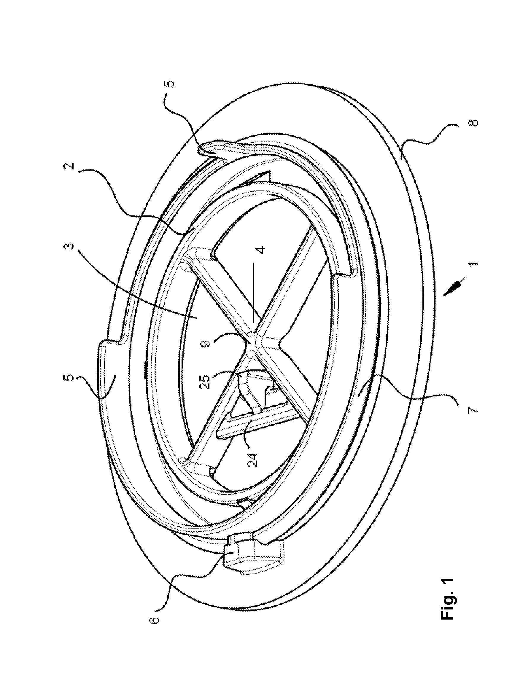
[0015]Referring to the drawings in particular, FIG. 1 shows a valve seat 1 with a flat sealing surface 2, which surrounds an opening 3 through which the gas flows. Opening 3 is divided into four sectors by a valve cross 4. An upright edge 5, which is interrupted in some areas and receives a valve membrane, not shown in FIG. 1, is located around the sealing surface 2. The upright edge 5 is used to center the valve membrane in relation to the sealing surface 2. A centering projection 6 and a circular bead 7 are located on the outside of edge 5. The underside 8 of valve seat 1 is connected to a filter mask 22. The webs of the valve cross 4 intersect each other in a center 9. A counter-support 25 is located at a cross strut 24, which is fastened between two arms of the valve cross 4. In case of a valve membrane of round shape, the center 9 of the valve cross 4 coincides with the center of the surface of the valve membrane.

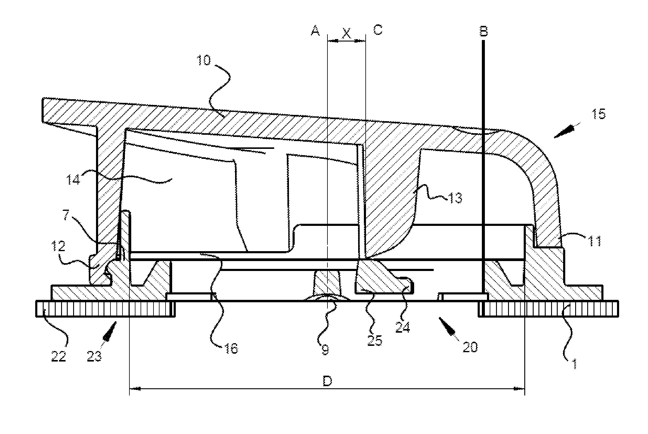
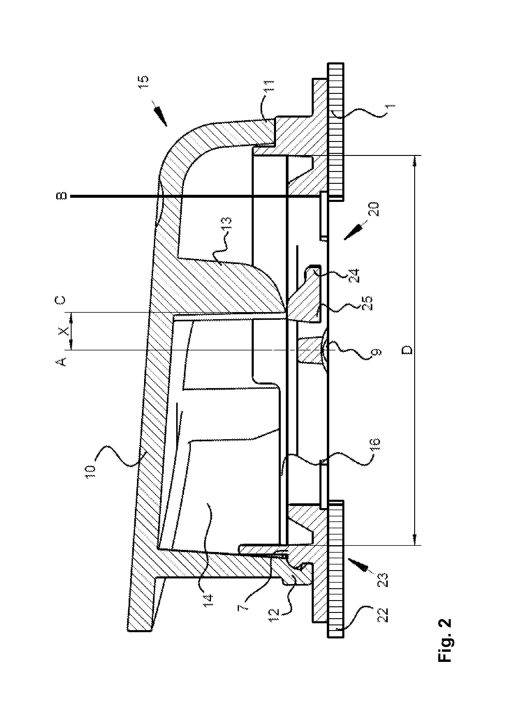
[0016]FIG. 2 shows the longitudinal section of a directional valv...


PUM


Abstract

A directional valve for a respirator product includes a valve housing (15) and a valve seat (1) for receiving a flexible valve membrane (16). The valve seat has a circular and essentially flat sealing surface (2) surrounding an opening (3), which is sealingly covered by the valve membrane during an inspiration phase. A fixing lug (13), on the valve housing (15), fixes the valve membrane in the valve seat and is arranged offset in relation to the center of the valve membrane, such that an entire circumferential surface of the valve membrane is lifted off from the sealing surface during an expiration phase. The fixing lug is directed essentially at right angles to a flow plane formed by the opening. A counter-support (25), within the opening, is arranged opposite the fixing lug such that the valve membrane is mounted with fixed clamping action, between the fixing lug and the counter-support.

Description

CROSS REFERENCE TO RELATED APPLICATIONS[0001]This application claims the benefit of priority under 35 U.S.C. §119 of German Patent Application DE 10 2012 018 277.5 filed Sep. 14, 2012, the entire contents of which are incorporated herein by reference.FIELD OF THE INVENTION[0002]The present invention pertains to a directional valve and to a respirator product with a directional valve.BACKGROUND OF THE INVENTION[0003]A respirator product in the form of a gas mask with port openings for filters as well as with an inspiration valve and with an expiration valve is known from DE 40 17 336 C1. Respirator filters can be arranged at different points of the half mask by means of a port adapter that can be fastened to a half mask in two preferential positions. The gas flow over the respirator filter is guided into the interior space of the mask to the mask user by means of directional valves, which are arranged both in the area of the respirator filter and at the gas outlet of the gas mask, an...

Claims


Application Information

Patent Timeline
IPC IPC(8): A62B18/10A62B23/02F16K15/14
CPCA62B18/10A62B23/025F16K15/14Y10T137/7888
Inventor ROSERT, MICHAELLESKE, DENNISHEYER, HARALDPANCUR, THOMAS
Owner DRAGER SAFETY
Why Eureka
Try Eureka