Micro Motor Locking System

a technology of locking system and micro-motor, which is applied in the direction of building locks, non-mechanical controls, constructions, etc., can solve the problems of excessive power consumption of bobbins during locking or unlocking, excessive consumption of bobbins for voltage, and burning of driving centres, etc., and achieve the effect of secure locking

Active Publication Date: 2010-10-07
VEMUS ENDUSTRIYEL ELEKTRONIK SANAYI & TICARET SIRKETI
View PDF27 Cites 17 Cited by
  • Summary
  • Abstract
  • Description
  • Claims
  • Application Information

AI Technical Summary

Benefits of technology

[0019]One of the most important purposes of th...

Problems solved by technology

Such bobbins consume too much power during locking or unlocking.
And this causes burning of driving centre.
In the known related art, too much power is consumed for the voltage and ampere values in locking systems and this causes short operating life of electronic locking systems.
However, in such systems lock can leave the housing easily that is, the locking distance is considerably short.
An...

Method used


Image

  • Micro Motor Locking System
  • Micro Motor Locking System
  • Micro Motor Locking System

Examples


Embodiment Construction

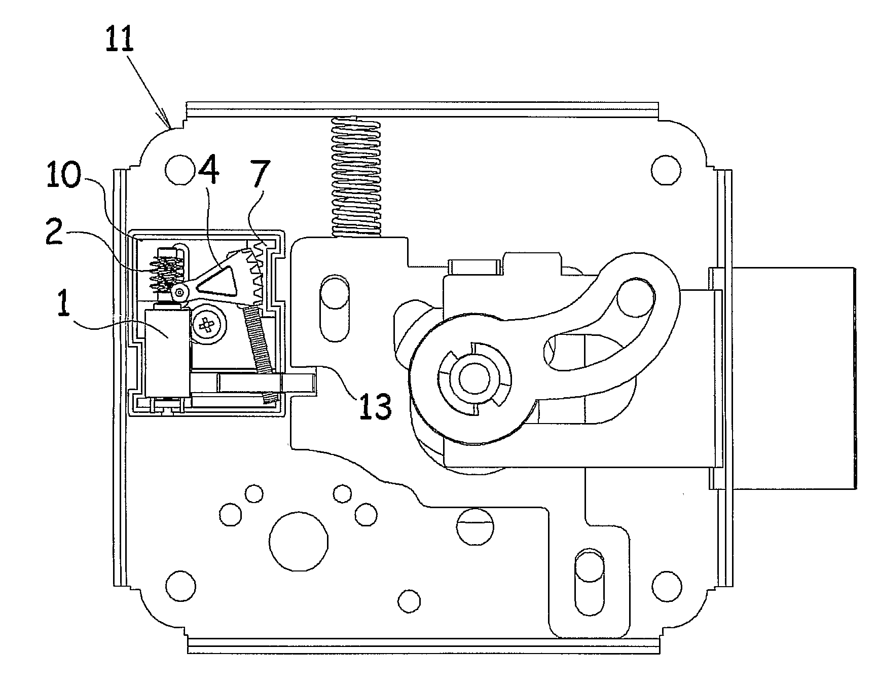
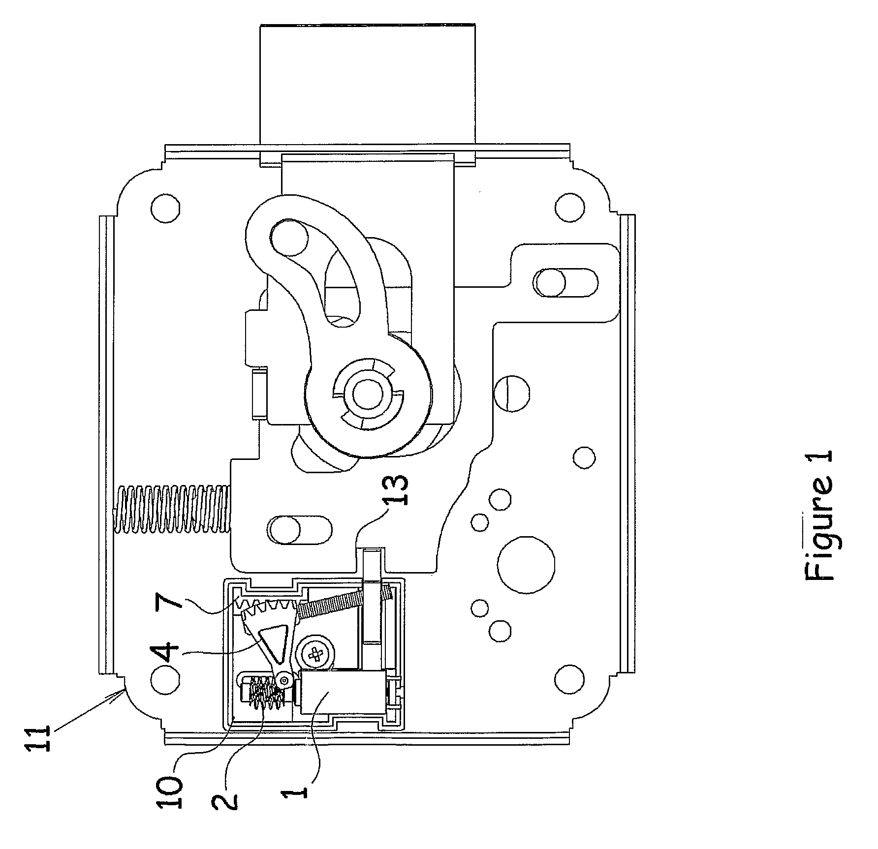
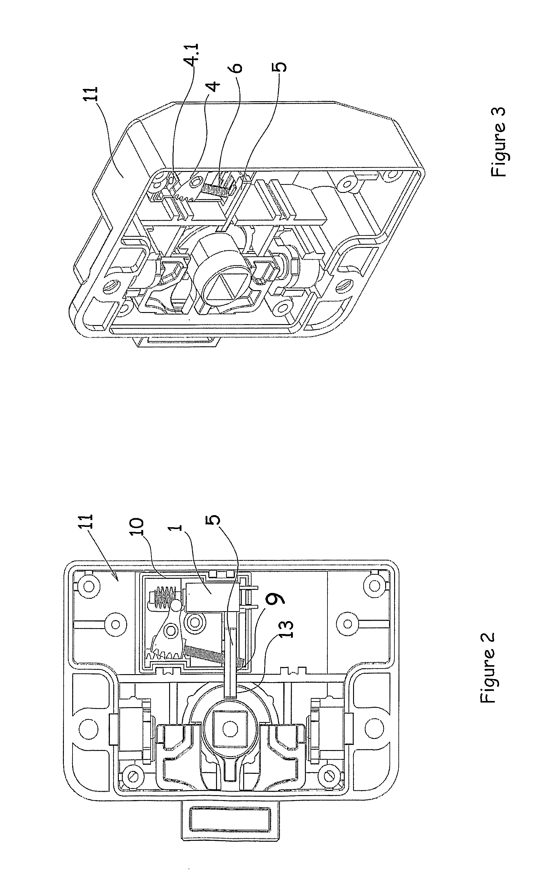
[0052]In this detailed description of the invention, the preferred embodiments of the micro motor locking system (8) being subject of this invention have been described only for the purpose of better understanding of the subject without any restrictive effects. FIG., 1, FIG. 2, FIG. 3, and FIG. 4 show lock samples where the micro motor lock system is used. Micro motor locking system (8) consists of motor (1) providing rotation motion, worm gear (2) converting the rotation motion into linear motion, linear motion member (3) following the said worm gear (2) and providing linear motion thereon, lock (5) entering in the lock housing (13) on the lock (11) and providing unlocking by means of removal from the housing (13), motion transmission member (6) moving the lock (5) up and down and providing entrance and removal of the lock (5) into / from housing (13) and thus providing locking; angular motion transmission member (4) supporting linear motion transmission member (3) and motion transmi...


PUM


Abstract

The invention relates to locking systems to realize locking function in embodiments such as electronic gates, drawers, cabinets, safes and similar things and it consists of linear motion transmission member (3) performing motion on a worm gear (2) to provide linear motion, angular motion transmission member (4) providing angular motion together with linear motion transmission member (3), guiding member (7) pushing, pulling and guiding angular motion transmission member (4) and linear motion transmission member (3) at the same alignment, motion transmission member (6) moving lock bolt (5) up and down, providing locking and unlocking, compressing the angular motion transmission member (4) in reverse direction and thus enabling the motor (1) to complete its cycle.

Description

THE RELATED ART[0001]The invention relates to micro engine locking system providing locking of embodiments such as electronic gate, drawers, cabinet, safe and similar ones, consisting of linear motion transmission member following the worm gear and moving linearly, angular motion transmission member providing increase in power and converting linear motion into angular motion, guiding member converting the motion received from the said angular motion member into linear motion and thus providing guidance, motion transmission member moving the lock up and down by use of the linear motion received from the guiding member and thus providing advantages such as lower power requirement, lower cost and secure locking distance.BACKGROUND OF THE RELATED ART[0002]Today it is known that embodiments such as electronic gate, drawers, cabinets, safe and similar things are used for controlled passing systems. In such types of locking systems the user enters his / her password by use of key set and the...

Claims


Application Information

Patent Timeline
IPC IPC(8): E05B47/06E05B15/04
CPCE05B47/0012E05B47/0603E05B47/0673E05B2015/0403E05B2047/0093E05B2015/0496E05B2047/0016E05B2047/0021E05B2047/0031E05B2015/0472Y10T70/7062Y10T70/7102Y10T70/7113Y10T70/713
Inventor DAYANIKLI, VEHBIDAYANIKLI, MUSTAFA
Owner VEMUS ENDUSTRIYEL ELEKTRONIK SANAYI & TICARET SIRKETI
Why Eureka
Try Eureka