Multi-functional aerial photography aircraft

An aircraft and multi-functional technology, applied in aircraft parts, transportation and packaging, etc., can solve the problems of no fixed focus head, target deformation, single fixed focus head, etc., and achieve convenient switching, convenient insertion and high alignment accuracy Effect

Active Publication Date: 2016-02-03
CHANGSHA UNIVERSITY
View PDF6 Cites 10 Cited by
  • Summary
  • Abstract
  • Description
  • Claims
  • Application Information

AI Technical Summary

Problems solved by technology

[0002] Rotor aerial photography aircraft is now widely used in aerial photography, surveying and other fields. The support and support arm (flying arm) of existing rotor aerial photography aircraft are generally rigidly connected and lack necessary buffering. Therefore, the vibration of the aircraft landing is relatively large. It is also easy to cause the aircraft to overturn, resulting

Method used


Image

  • Multi-functional aerial photography aircraft
  • Multi-functional aerial photography aircraft
  • Multi-functional aerial photography aircraft

Examples


Example Embodiment

[0063] Example 1:

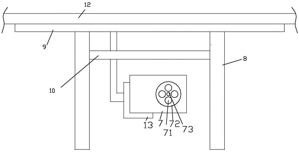
[0064] like Figure 1-7 , 9-10, a multifunctional aerial photography aircraft, including a bracket 12, a rotor, a base plate 9, a cloud platform 13, legs 8 and a camera 7;

[0065] The rotor and the platform are set on the bracket;

[0066] The bottom plate is fixed at the bottom of the bracket; the camera is installed on the gimbal;

[0067] The outriggers are fixed to the bottom of the base plate;

[0068] The camera includes a fuselage 77 and a composite lens 72; a CCD sensor 76 is provided in the fuselage, and a photoelectric transmitting and receiving device 75 for lens alignment is provided on the fuselage;

[0069] The composite lens is provided with a rotating shaft 73; 4 sub-lenses 71 are integrated in the composite lens; the sub-lenses are evenly arranged along the circumference of the composite lens; A light reflection sheet 74 is provided; a stepping motor for driving the lens to rotate is also provided in the fuselage. There can be multipl...

Example Embodiment

[0087] Example 2:

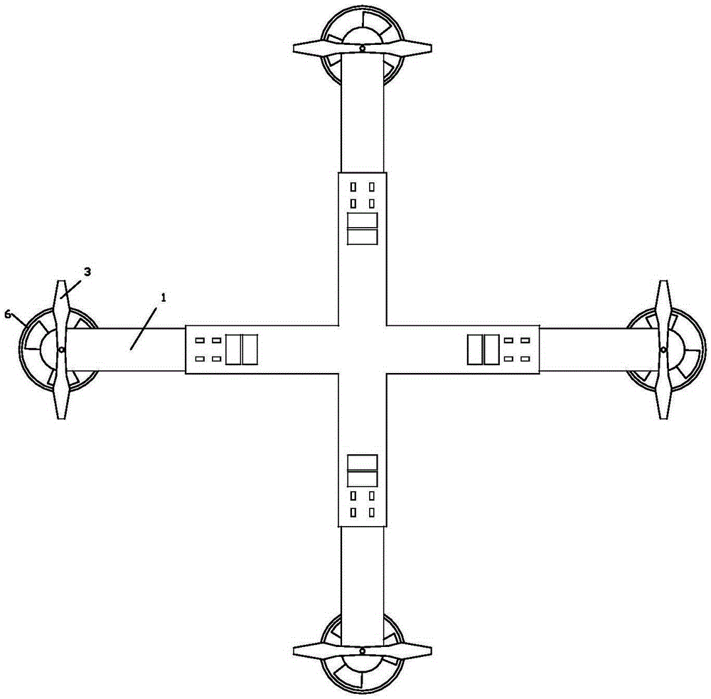
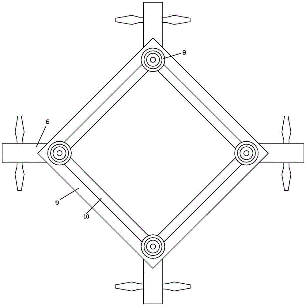
[0088] like figure 1 , 4, 8-10, except that the brackets are different, the scheme of Example 2 is the same as that of Example 1. The support of this embodiment is a hexagonal star-shaped support composed of 6 transverse struts of the same length; each corner of the hexagonal star-shaped support is provided with a rotor.

[0089] Rotor includes main rotor and auxiliary rotor;

[0090] The outer end of the outer arm is provided with a main rotor 3 and an auxiliary cantilever 6; the main rotor and the auxiliary cantilever are coaxially arranged, and the main rotor is located above the outer arm, and the auxiliary rotor is located below the outer arm;

[0091] The blade diameter of the main rotor is larger than that of the auxiliary rotor;

[0092] The auxiliary rotor is a ducted fan, and the auxiliary rotor is fixed on the bottom of the outer arm by the ducted fan fixing part 7 .

[0093] Furthermore, a rotor is provided at each intersection of the hexago...


PUM


Abstract

The invention discloses a multi-functional aerial photography aircraft. The multi-functional aerial photography aircraft comprises a support (12), rotor wings, a base plate (9), a holder (13), supporting legs (8) and a camera (7); the rotor wings and the holder are arranged on the support; the base plate is fixed to the bottom of the support; the camera is installed on the holder; the supporting legs are fixed to the bottom of the base plate; the camera comprises a camera body (77) and a combined type lens (72); a CCD sensor (76) is arranged in the camera body, and a photoelectric transmitting and receiving device (75) used for aligning the lens is arranged on the camera body. The multi-functional aerial photography aircraft is high in integration degree and compact in structure, has the flight structure excellent in performance and is further provided with the supporting legs having the unique buffering function, furthermore, the aircraft is provided with the camera of original creation, and therefore the multi-functional aerial photography aircraft is abundant in function, high in safety, ingenious in structure, large in lift force, stable in flight and easy to implement.

Description

technical field [0001] The invention relates to a multifunctional aerial photography aircraft. Background technique [0002] Rotor aerial photography aircraft is now widely used in aerial photography, surveying and other fields. The support and support arm (flying arm) of existing rotor aerial photography aircraft are generally rigidly connected and lack necessary buffering. Therefore, the vibration of the aircraft landing is relatively large. It is also easy to cause the aircraft to overturn, resulting in damage to the relevant equipment on the aircraft, and the safety is poor; [0003] In addition, the existing aerial vehicles generally have a single fixed-focus head or zoom head. Although the zoom head can flexibly adjust the focal length, the overall quality is not as high as the fixed-focus head, and the imaging of the target object is prone to deformation during the zooming process. ; [0004] Therefore, be necessary to design a kind of brand-new multifunctional aeri...

Claims


Application Information

Patent Timeline
IPC IPC(8): B64D47/08
Inventor 刘亮邓名高孙利平张海涛
Owner CHANGSHA UNIVERSITY
Why Eureka
Try Eureka