Method and apparatus for the time controlled activation of elements

a technology of time control and activation method, applied in the direction of time interval measurement, instrumentation, primary cell maintenance/service, etc., can solve the problem of rather limited activation area

Active Publication Date: 2010-10-07
WESTFALISCHE WILHELMS UNIV MUNSTER
View PDF3 Cites 21 Cited by
  • Summary
  • Abstract
  • Description
  • Claims
  • Application Information

AI Technical Summary

Benefits of technology

[0008]Further this change in physical properties can be used to activate elements such as a display element, an electrical switch, a time controlled resistor, a galvanic cell or any combination thereof. The activation of the display element can be switched in a time dependent way. Similarly a galvanic cell can be made accessible as an energy storage after a certain period of time has elapsed. In one aspect of the invention, it is possible to start the activation of the element automatically simply by establishing the contact of the apparatus with water vapours. Therefore the apparatus can be stored for a long period without being activated once a reservoir containing the fluid is filled. The apparatus would further display the time-temperature integral the apparatus is exposed to as well as the time it is exposed thereto. This may be of particular relevance for samples where time and temperature are critical such as for example blood samples. The change in resistance allows for the apparatus also to be used as a time dependent switch or a time controlled resistor.
[0009]The present invention differs from the prior art in that essentially the whole activation layer is available for the activation of the elements which is induced by a migrating fluid and not by an electrical current. The apparatus of the invention further allows the triggering of electrical switching after time has lapsed and is dependent on the extent of activation reached within the activation layer. The apparatus further allows the use of control functions which are governed by the extent of activation within the activation layer. The apparatus of the invention allows the implementation of a temperature dependence into the behaviour of the apparatus. The temperature dependence of the apparatus is given by the temperature dependence of the migration velocity of the fluid within the migration layer.

Problems solved by technology

The area available for activation is rather limited, though.

Method used


Image

  • Method and apparatus for the time controlled activation of elements
  • Method and apparatus for the time controlled activation of elements
  • Method and apparatus for the time controlled activation of elements

Examples


Embodiment Construction

[0052]For a complete understanding of the present invention and the advantages thereof, reference is now made to the following detailed description taken in conjunction with the figures.

[0053]It should be appreciated that the various aspects of the invention discussed herein are merely illustrative of the specific ways to make and use the invention and do not therefore limit the scope of the invention when taken into consideration with the claims and the following detailed description. It will also be appreciated that features from some aspects of the invention may be combined with features from other aspects of the invention.

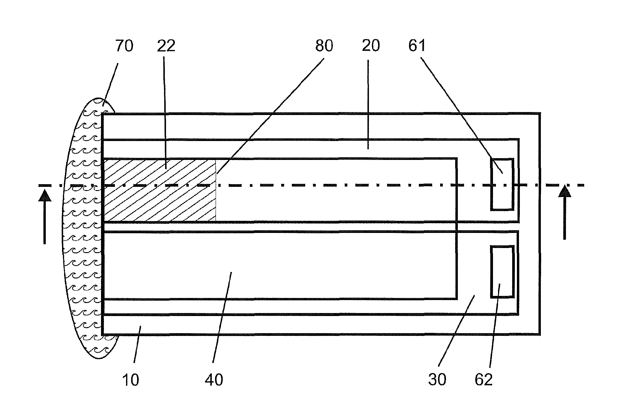
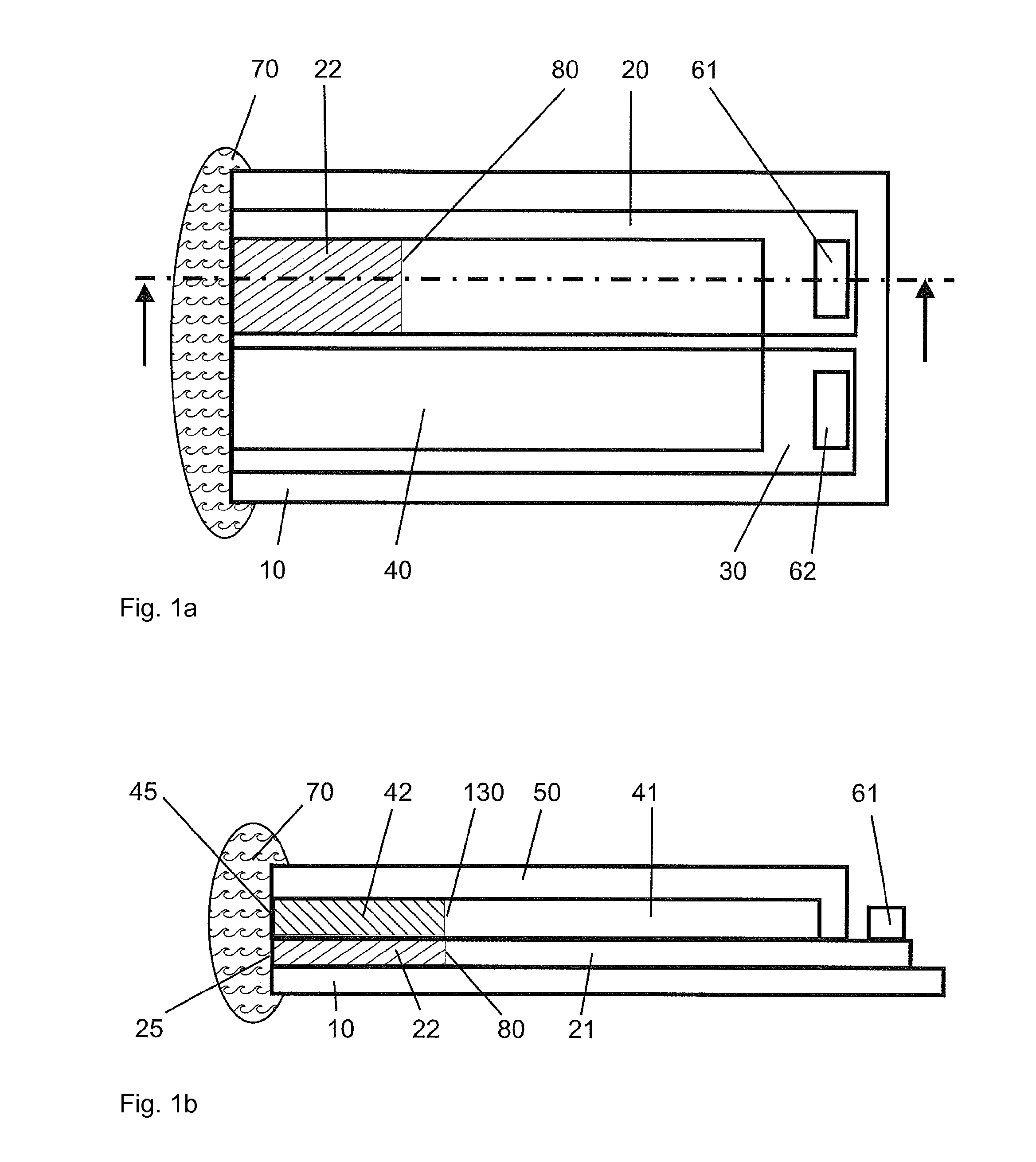
[0054]FIG. 1 shows a first embodiment of an apparatus 1 according to the invention in a top view (FIG. 1a) and a cross-sectional view (FIG. 1b). The position of the cross-sectional view (FIG. 1b) is shown in FIG. 1a by means of a dashed-dotted line and a direction of the cross-sectional view is indicated by two arrows.

[0055]FIG. 1 shows a substrate 10 which is ...


PUM


Abstract

An apparatus (1) for activation of at least one element is disclosed. The apparatus (1) comprises at least one activation layer (20), at least one migration layer (40) arranged at the at least one activation layer (20) and being permeable to a fluid (70). The fluid (70) causes in use a change of doping level in the at least one activation layer (20) which activates the at least one element. The element may comprise an electrochromic display element (220), an electrical switch, a time controlled resistor, a galvanic element (210) or any combination thereof.

Description

FIELD OF THE INVENTION[0001]The invention relates to a method and apparatus for the time controlled activation of elements such as electrical switches, control elements, electrochromic display elements, galvanic cells and transistors.BACKGROUND TO THE INVENTION[0002]Conductive polymers have been studied for several years now as candidates to partly replace silicon-based electronic systems. An electrochemical transistor engineered using conductive polymers has been disclosed, for example, by Nilsson et al., Adv. Mater. 14, No. 1, 2002, p. 51. Moreover, an electrochemical transistor engineered using conductive polymers has been demonstrated in combination with display elements comprising conductive polymer material by P. Andersson et al., Adv. Mater. 14, No. 20, 2002, 1460.[0003]Electrochemical devices implemented using conductive polymers react more slowly than those electronic devices implemented in silicon. Therefore the electrochemical devices based on conductive polymers seem sui...

Claims


Application Information

Patent Timeline
Patent Type & Authority Applications(United States)
IPC IPC(8): G01D21/00B05D1/36B05D5/12B05D5/06
CPCG02F1/1525G02F1/163H01M6/5044H01M6/40H01M6/38G02F1/153G04F13/04H01G9/00
Inventor KNOLL, MEINHARD
Owner WESTFALISCHE WILHELMS UNIV MUNSTER
Why Eureka
Try Eureka