Method and system for laser projection and holographic diffraction grating for a vehicle

a laser projection and holographic diffraction technology, applied in the field of method and system for projecting images, can solve the problem that the light used in vehicles (be they cars, vans or even boats) is limited to providing ligh

Inactive Publication Date: 2010-10-07
DOUGLAS RALPH PAUL
View PDF18 Cites 46 Cited by
  • Summary
  • Abstract
  • Description
  • Claims
  • Application Information

AI Technical Summary

Benefits of technology

[0018]The image creation means receives the beam of light from the light beam source and allows the beam of light to pass through the image so as to project the image upon the desired surface. The light diffraction image itself can be a message, logo, or graphic design. The image creation means can comprise a micro-lithograph secured to the laser diode assembly, wherein the micro-lithograph comprises has an image thereupon. Or, the image creation means can comprise a collimated beam, generated by the laser diode assembly, and shining through a holographic diffraction grating.
[0019]It is important to note that the means for deriving the beam of light, though adaptable to a laser diode module, can be derived from: high intensity LEDs; bare die LEDs which are powered through thin film coatings and concentrated by various means known to the art; and, the like.
[0020]The installing step further comprises installing the laser diode assembly in a side view mirror assembly, or a door panel assembly, of the vehicle. The laser diode assembly could be mounted in any vehicle panel or area that allows the laser diode assembly to project the light diffraction image through an opening onto the selected surface. If the assembly is mounted in the side view mirror, then the assembly is secured to the inside of the mirror so as to project the image downward from a hole in the bottom portion of the side view minor. If the laser diode assembly has been mounted in a door panel, then the assembly is positioned so as to project the light diffraction image through an opening located in a bottom portion of the door panel and passing therethrough to the selected surface.

Problems solved by technology

The lighting used in vehicles (be they cars, vans or even boats) is limited to providing light only.

Method used


Image

  • Method and system for laser projection and holographic diffraction grating for a vehicle
  • Method and system for laser projection and holographic diffraction grating for a vehicle
  • Method and system for laser projection and holographic diffraction grating for a vehicle

Examples


Embodiment Construction

[0033]Reference will now be made in detail to several embodiments of the invention that are illustrated in the accompanying drawings. Wherever possible, same or similar reference numerals are used in the drawings and the description to refer to the same or like parts or steps. The drawings are in simplified form and are not to precise scale. For purposes of convenience and clarity only, directional terms, such as top, bottom, up, down, over, above, and below may be used with respect to the drawings. These and similar directional terms should not be construed to limit the scope of the invention in any manner. The words “connect,”“couple,” and similar terms with their inflectional morphemes do not necessarily denote direct and immediate connections, but also include connections through mediate elements or devices.

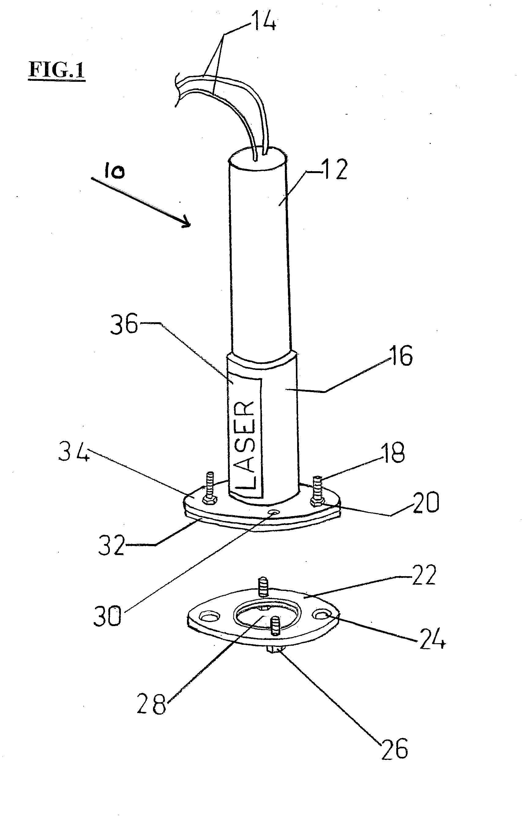
[0034]Turning to FIG. 1, there is shown a perspective depiction of a laser projection assembly 10 of the type compatible with the present invention.

[0035]The Laser assembly 1...


PUM


Abstract

The present invention is a method and system for projecting an image from a vehicle onto a surface, such as a road or sidewalk. A laser diode assembly is installed in the vehicle and comprises: a light beam source; a power source; a power regulating chip; an image creation means; and, power activating means. A lens is secured to an output end of the laser diode assembly, and comprises a light diffraction image which can be a message, logo, or graphic design Activation is initiated by switching on the assembly from a position within the interior of the vehicle, or by an activity such as the opening of a door. The activation is ramped up to a full-on state over a pre-set period of time.

Description

CROSS REFERENCE TO RELATED APPLICATION[0001]This application is related to, and claims priority from, U.S. Provisional Application Ser. No. 61 / 207,513 filed Feb. 13, 2009, the entire contents of which is incorporated herein by reference.BACKGROUND OF THE INVENTION[0002]1. Field of the Invention[0003]The present invention relates to a method and system for projecting an image from a vehicle onto a surface. More specifically, the present invention relates to a method and system of causing a laser generated beam of light to pass through a lens having an image thereon, and casting the image on a surface such as a road, curb, or vehicle appendage.[0004]2. Description of the Related Art[0005]The related art involves the lighting industry generally, and recreational or safety lighting in particular. The automotive industry has an extensive aftermarket or custom lighting culture. The use of inexpensive, packaged light emitting diodes (LEDs) in sheets, strips, or individually, have allowed c...

Claims


Application Information

Patent Timeline
Patent Type & Authority Applications(United States)
IPC IPC(8): G03B21/20G03B21/14
CPCB60Q2400/50G03B21/14B60R2001/1215G03H2001/0055G03H2001/2234
Inventor DOUGLAS, RALPH PAUL
Owner DOUGLAS RALPH PAUL
Why Eureka
Try Eureka