Guideway illuminator

Active Publication Date: 2010-10-07
OSRAM SYLVANIA INC
View PDF13 Cites 2 Cited by
  • Summary
  • Abstract
  • Description
  • Claims
  • Application Information

AI Technical Summary

Benefits of technology

[0005]It is another object of the invention to enhance the lighting of difficult to light areas.
[0006]Yet another object of the invention is the improvement of lighting in difficult to light

Problems solved by technology

While these previous devices have all provided some benefit, they suffer from complicated installation, high cost and difficult maintenance.
Further, many e

Method used


Image

  • Guideway illuminator
  • Guideway illuminator
  • Guideway illuminator

Examples


Embodiment Construction

[0020]For a better understanding of the present invention, together with other and further objects, advantages and capabilities thereof, reference is made to the following disclosure and appended claims taken in conjunction with the above-described drawings.

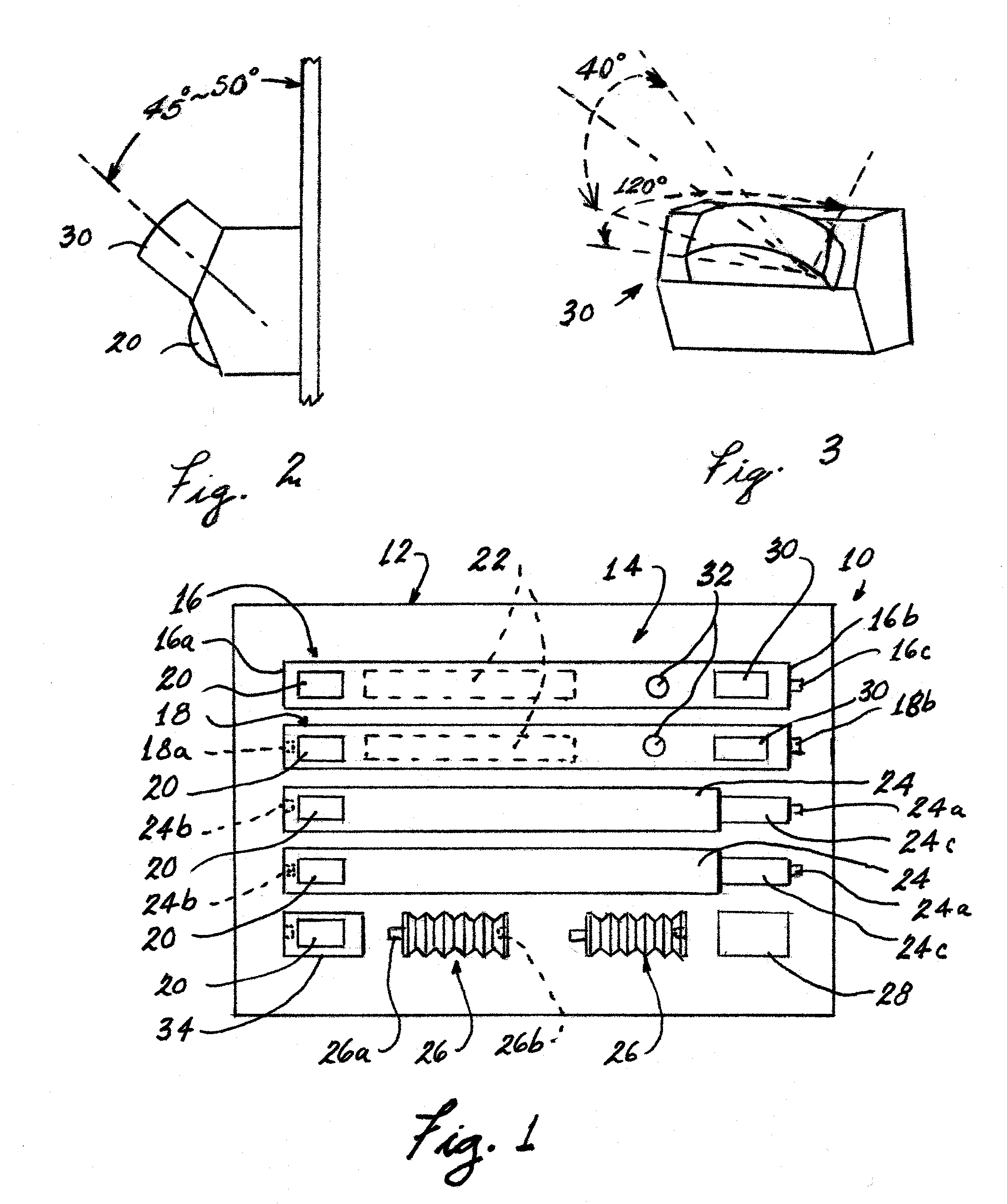
[0021]Referring now to the drawings with greater particularity, there is shown in FIG. 1 a guideway illuminator kit 10 comprising a container 12 and a number of assembleable parts 14 within the container. The assembleable parts comprise a first member 16 and a second member 18 each having at least one light source 20. While the choice of light sources is large, in the preferred embodiment of the invention the light sources are light emitting diodes (LED or LEDs) whose long life and low power requirements are ideal for this situation. At least one of the first member 16 and the second member 18 receive a power source 22. Again, while it is possible to employ conventional house current to operate the system, in a preferred embodime...


PUM


Abstract

A guideway illumination system (100) comprises a first member (16) and a second member (18) each having at least one light source (20) and at least one of the first member (16) and the second member (18) receiving a power source (22). The first member (16) has a closed end (16a) and a connecting end (16b) and the second member has two connecting ends (18a 18b). At least one intermediate member (24) has at least one light source (20) and a male connecting end (24a) and a female connecting end (24b). At least one flexible joining member (26) is also provided, the flexible joining member being capable of bending at least 90° and being joinable to any of the first and second end members and the intermediate members.

Description

TECHNICAL FIELD[0001]This invention relates to guideway illuminators and more particularly to automatic guideway illuminators. Still more particularly it relates to guideway illuminators for difficult to light areas such as stairways.BACKGROUND ART[0002]Many procedures have been suggested for illuminating difficult to traverse areas, such as stairways, hallways and closets, from simple light bulbs mounted in ceiling fixtures to complicated structures for illuminating stair edges, treads or risers, the latter often being employed in theaters. (See, for example, U.S. Pat. Nos. 6,685,332, 6,606,827 and 6,145,996). Suggested operating mechanisms for these lighting arrays run the gamut from wall-mounted, user-activated switches to various forms of motion detectors that automatically activate the light sources.[0003]While these previous devices have all provided some benefit, they suffer from complicated installation, high cost and difficult maintenance. Further, many employ normal househ...

Claims


Application Information

Patent Timeline
IPC IPC(8): B60Q1/124
CPCB66B23/225E04F11/1804E04F2011/1872F21Y2103/00F21V21/32F21V33/006F21V21/005E04F11/1808Y10S362/802
Inventor COUSHAINE, CHARLES M.KONG, KHOR YONGBEASLEY, DANIEL
Owner OSRAM SYLVANIA INC
Why Eureka
Try Eureka