Percutaneous Implantable Nuclear Prosthesis

a nuclear prosthesis and implantable technology, applied in the field of body implantable devices, can solve the problems of disc desiccation, nerve roots irritation, loss of disc space height and pressure, etc., and achieve the effect of improving the stability and stability of the nerve roo

Active Publication Date: 2010-10-07
SPINAL STABILIZATION TECH
View PDF63 Cites 65 Cited by
  • Summary
  • Abstract
  • Description
  • Claims
  • Application Information

AI Technical Summary

Benefits of technology

[0017]The present invention overcomes the deficiencies of prior nuclear motion prostheses, offers several advantageous properties, and provides a system for sizing, forming, delivering, and deploying a nuclear prosthesis into the inter-vertebral disc space. The percutaneously implantable nuclear prosthesis, formed in accordance with the present invention, utilizes the advantages of both a textile prosthesis and a polymer prosthesis to create a compartmentalized composite structure, having characteristics closely resembling the properties of a healthy native inter-vertebral disc. The nuclear prosthesis is comprised of an annular structure and a nuclear structure. The annular structure comprises an annular enclosing layer which defines an annular enclosure, an annular reinforcement band adjacent the periphery of the annular enclosing layer, a sealing valve core disposed within the annular enclosure and adjacently attached to the annular enclosing layer, and in-situ curable rubber, which is injected into the annular enclosure. The nuclear structure comprises a nuclear enclosing layer which defines a nuclear enclosure and an indwelling catheter mounted and bonded to a neck portion of the nuclear enclosing layer, and extends distally into, and is enclosed within the nuclear enclosure.

Problems solved by technology

Disc desiccation is associated with loss of disc space height and pressure.
Leakage of the nuclear material can cause irritation of the nerve roots by both mechanical and biochemical means.
Eventually, degenerative instability is created, leading to both spinal canal and neuroforaminal stenosis.
The advent of spinal fusion and the proliferation of surgical instrumentation and implants has led to an exponential utilization of expensive new technologies.
However, many spinal surgeons remain skeptical about the positive claims regarding MISS, citing certain drawbacks, including increase in operating room time, requirement for expensive proprietary instruments, increased cost, and the technically demanding nature of the procedure.
Fusion prostheses intended for MISS insertion offer few if any advantages over those for open surgical technique.
Greater degrees of stress are transmitted above and below the treated segment, often leading to accelerated degeneration of adjacent discs, facet joints, and ligaments (adjacent level degeneration).
Removal of these structural spinal elements causes destabilization of the spinal segment.
Prior nuclear motion prosthesis designs also fail to provide the outer margin of the nuclear prosthesis with surface and structural properties that encourage native tissue ingrowth.
However, prior annular bands are non-compliant.
This is disadvantageous because it reduces the radial outer expansion required for load dampening.
The result is that the end plates eventually fail, resulting in loss of intradiscal pressure, accelerated degeneration, and subsidence of the nuclear prosthesis.
These prostheses tend to exert untoward pressure on an already weakened annulus fibrosis.
Particularly, such a prosthesis tends to protrude into a pre-existing annular tear.
Other designs fail to incorporate or use a central gas cushion with a valve system or assembly that does not leak.
Another problem with prior nuclear motion prostheses is the imprecise sizing and tailoring of the nuclear prosthesis.
Over sizing places unnecessary stress on the already damages and degenerated annulus fibrosis, while under sizing of the nuclear prosthesis may result in inadequate contact with the inner wall of the annulus fibrosis, and possibly non-integration and migration of the nuclear prosthesis.
Other designs of nucleus motion prostheses suffer draw backs such as bulkiness, inelasticity, inability to fold and pack the nuclear prosthesis into a delivery cannula or apparatus for percutaneous implantation into a patient.

Method used


Image

  • Percutaneous Implantable Nuclear Prosthesis
  • Percutaneous Implantable Nuclear Prosthesis
  • Percutaneous Implantable Nuclear Prosthesis

Examples


Embodiment Construction

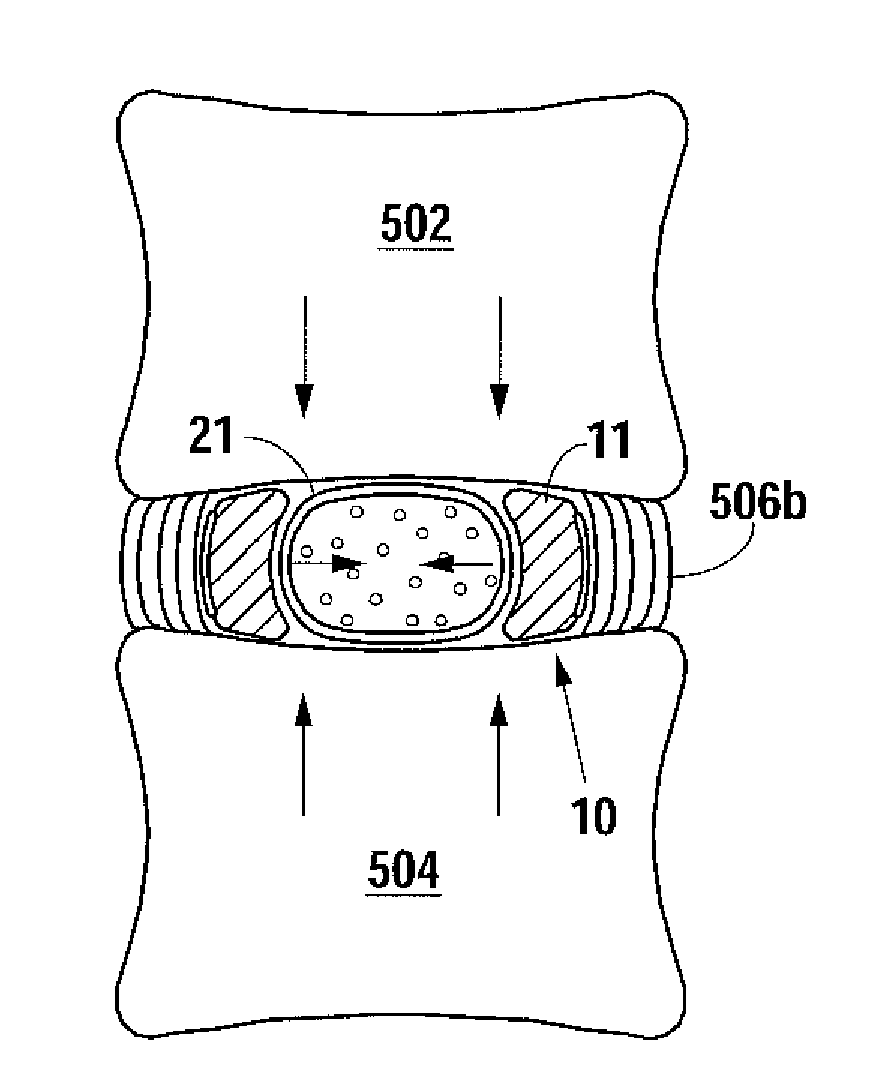
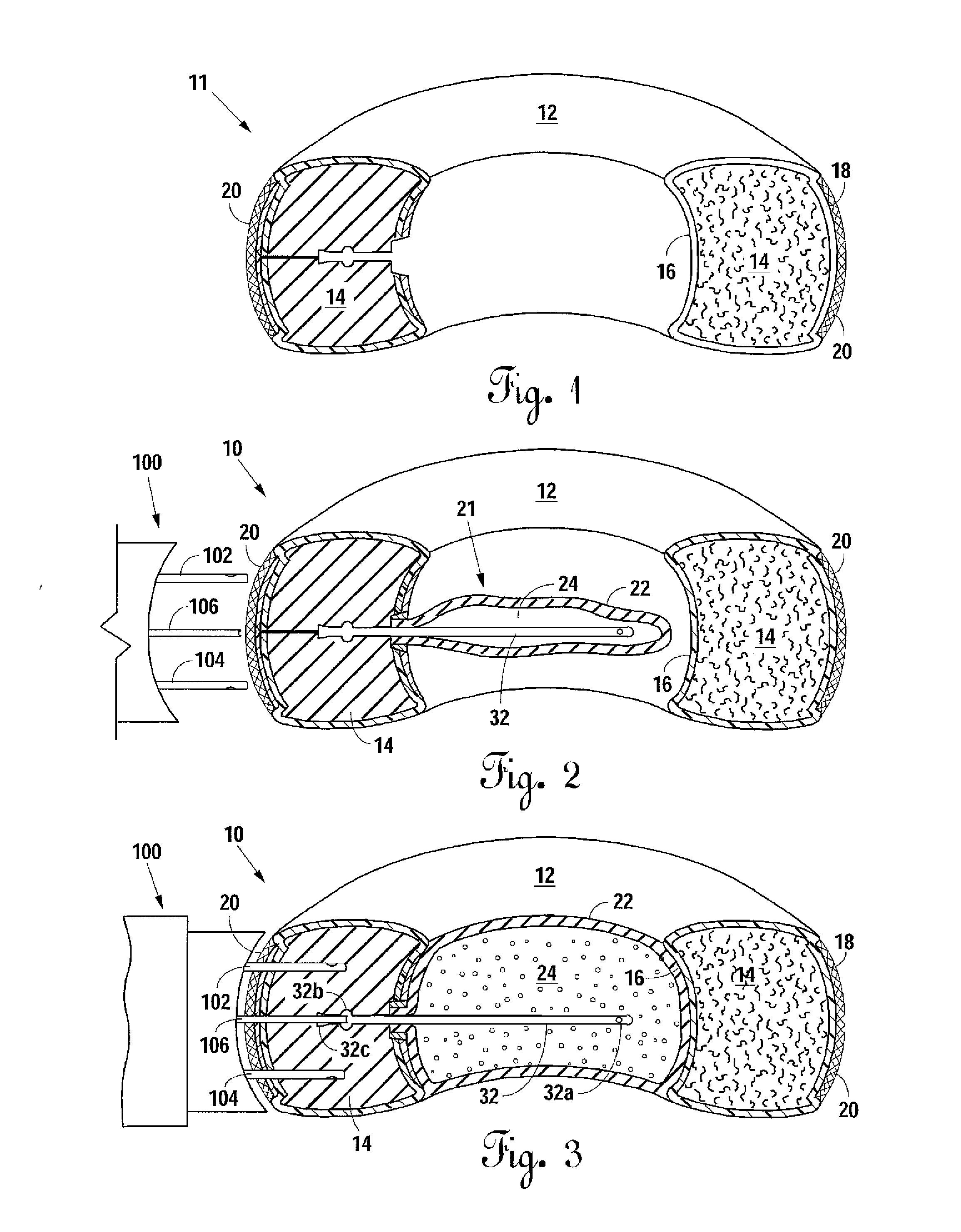
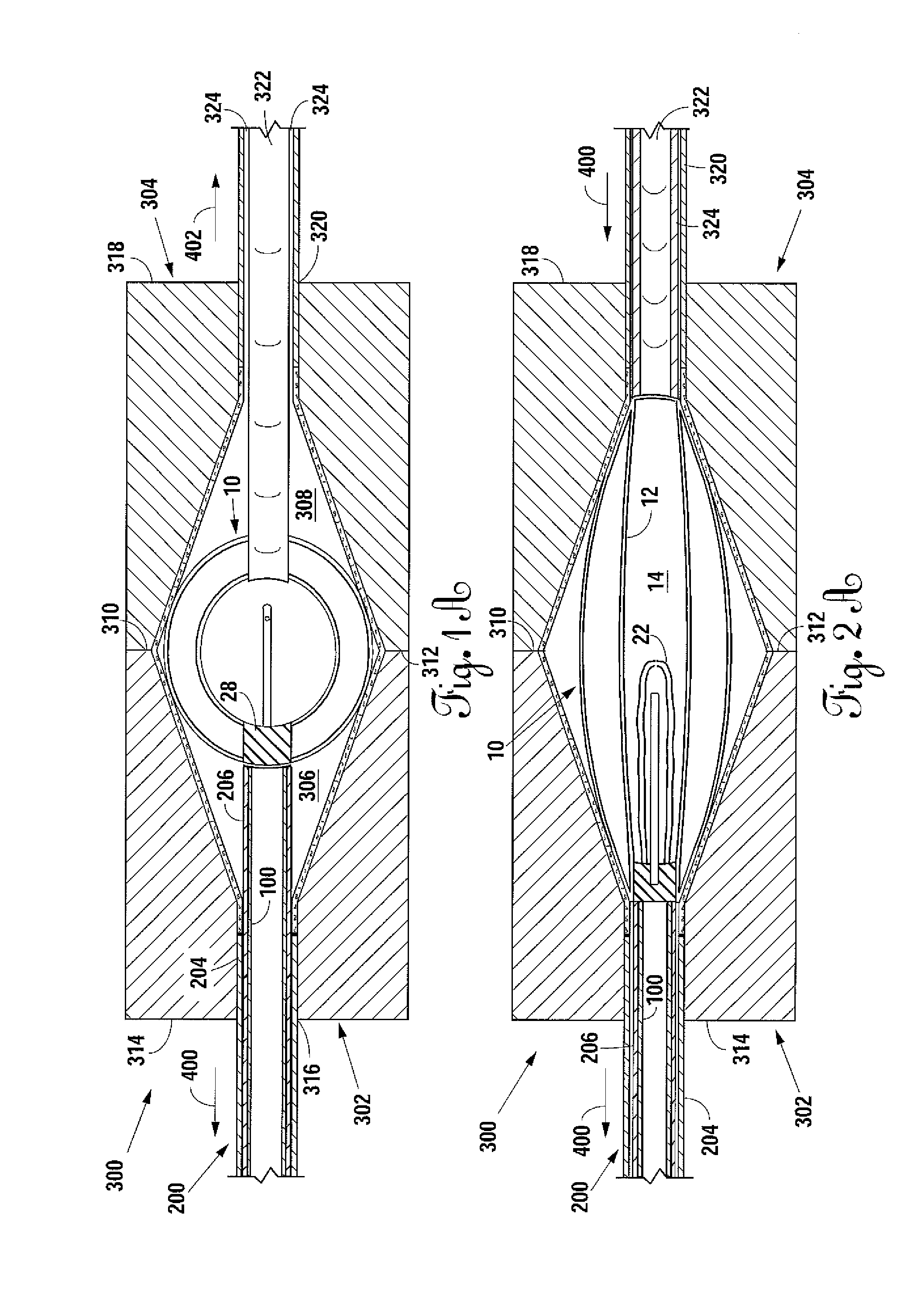
[0074]Referring to FIGS. 1 through 4 the nuclear prosthesis 10 of the present invention is disclosed. Nuclear prosthesis 10 comprises an annular structure 11 and a nuclear structure 21. Annular structure 11 comprises an annular enclosing layer 12 defining an annular enclosure 14, and nuclear structure 21 comprises a nuclear enclosing layer 22 defining a nuclear enclosure 24. Nuclear enclosing layer 22 is disposed adjacent annular enclosing layer 12 in the central space defined by annular enclosing layer 12, along an inner margin 16 thereof. Annular structure 11 of nuclear prosthesis 10 further comprises an annular reinforcement band 20 contiguous with or adjacent a peripheral or outer margin 18 of the inflatable annular enclosing layer 12 and a sealing valve core 28 of a sealing valve assembly 26. Annular enclosing layer 12 incorporates the sealing valve core 28 and annular enclosure 14 filled in-situ with curable rubber. In its inflated state, nuclear prosthesis 10 is substantially...


PUM

PropertyMeasurementUnit
thickaaaaaaaaaa
shapeaaaaaaaaaa
compressibleaaaaaaaaaa

Abstract

An inter-vertebral disc prosthesis intended for percutaneous deployment comprises an expandable annular enclosure and an expandable nuclear enclosure. The expandable annular enclosure incorporates a reinforcing annular band along its periphery and is filled with in-situ curable rubber. The expandable nuclear enclosure is filled with a gas. The nuclear prosthesis further incorporates a novel, integrally molded sealing valve assembly and is stretchable and collapsible into a minimal profile for ease of insertion into a specially designed delivery cannula, and is inflation-assisted expandable into an inter-vertebral disc in which complete percutaneous nuclectomy has been performed.

Description

CROSS REFERENCE TO RELATED APPLICATIONS[0001]This is a utility application claiming priority to U.S. Provisional Application Ser. No. 61 / 212,104 filed Apr. 7, 2009, and incorporated herein by reference.BACKGROUND OF THE INVENTION[0002]1. Field of the Invention[0003]The present invention generally relates to body-implantable devices. More particularly, the present invention relates to a percutaneously insertable and expandable inter-vertebral disc prosthesis. Specifically, the present invention comprises a novel nuclear prosthesis, a specially designed delivery apparatus, and a loading apparatus for loading the nuclear prosthesis within the delivery apparatus.[0004]2. Description of the Related Art[0005]The role of the inter-vertebral disc in spine biomechanics has been the subject of extensive research and is generally well understood. A typical native spinal unit is shown for exemplary purposes in FIG. 22A. The functional spinal unit, or spinal motion segment 500 consists of two ad...

Claims


Application Information

Patent Timeline
Patent Type & Authority Applications(United States)
IPC IPC(8): A61F2/44
CPCA61F2/441A61F2250/0028A61F2002/30006A61F2002/30009A61F2002/30074A61F2002/30563A61F2002/30583A61F2002/30584A61F2002/30586A61F2002/444A61F2002/4495A61F2210/0057A61F2210/0085A61F2250/0015A61F2/4611A61F2/442A61F2002/30069
Inventor HIBRI, NADI S.LUTZ, JAMES D.
Owner SPINAL STABILIZATION TECH
Why Eureka
Try Eureka