
Thermostat

a technology of thermostats and insulating plates, applied in the field of thermostats, can solve problems such as contact defects, contact defects, contact abnormal flow, etc., and achieve the effects of reducing impact, preventing damage, and minimizing damage thereto

Inactive Publication Date: 2010-10-14
HANBECTHISTEM
View PDF13 Cites 4 Cited by
  • Summary
  • Abstract
  • Description
  • Claims
  • Application Information

AI Technical Summary

Benefits of technology

[0017]It is still another object of the present invention to provide a thermostat that prevents damage to an electrical device and a fire due to overheating by blocking overheating twice.
[0018]It is yet another object of the present invention to provide a thermostat that ensures safe flow and blocking of a current.
[0042]Furthermore, the two contact points can reduce an impact applied to the contact points when the contact points contact with each other, thereby minimizing damage thereto.
[0043]In addition, the thermostat according to the present invention prevents damage to an electrical device and a fire due to overheating by blocking overheating twice.
[0044]That is, safe flow and blocking of a current can be guaranteed.
[0045]Moreover, when the thermostat according to the present invention fails to block overheating first, it can block overheating secondarily at a little higher temperature by setting the operation point of the second switching section to be higher than the operation point of the first switching section.

Problems solved by technology

In general, although electrical devices are safely operated by a certain range of currents or within a certain range of temperatures during a normal operation, they may be damaged or cause a fire due to overheating when an over-current is supplied to them or they are overheated by an abnormal operation.
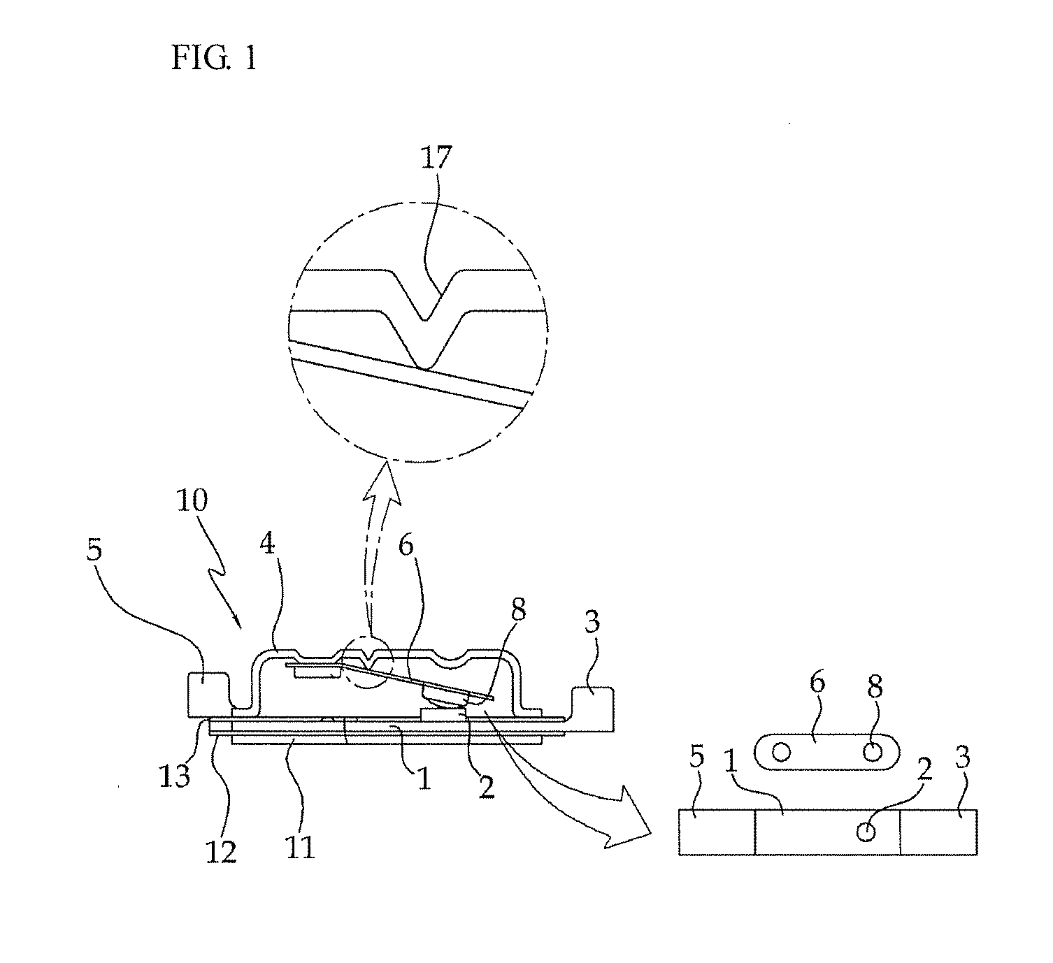
However, since the thermostat 10 has a single fixed contact point 2 and a single movable contact point 8, a current may be abnormally flow when a surface of the fixed contact point 2 or the movable contact point 8b is stained with foreign substances and carbon may be deposited on the surfaces of the fixed contact point 2 and the movable contact point 8, causing contact defects after they are used for a long time.
In addition, impacts or metal fatigues between the fixed contact point 2 and the movable contact point 8 may deform the contact points 2 and 8, causing contact defects.
Accordingly, as the number of thermostats increases, manufacturing costs also increase and the circuit is made relatively complex.
This phenomenon causes damage to the electrical product or a fire due to overheating.
That is, since the conventional thermostat does not disclose a structure of preventing a plurality of overheating (over-current) situations, it completely loses an intrinsic function of preventing an overheating (over-current) problem even when it is out of order or abnormally operated.
Therefore, the user that needed a plurality of dual blocking devices has undergone the inconvenience of constituting circuits and parts separately.
Meanwhile, the conventional dual blocking device may cause an undesirable situation due to its complex structure and process, deteriorating reliability and productivity.

Method used


Image

  • Thermostat
  • Thermostat
  • Thermostat

Examples


first embodiment

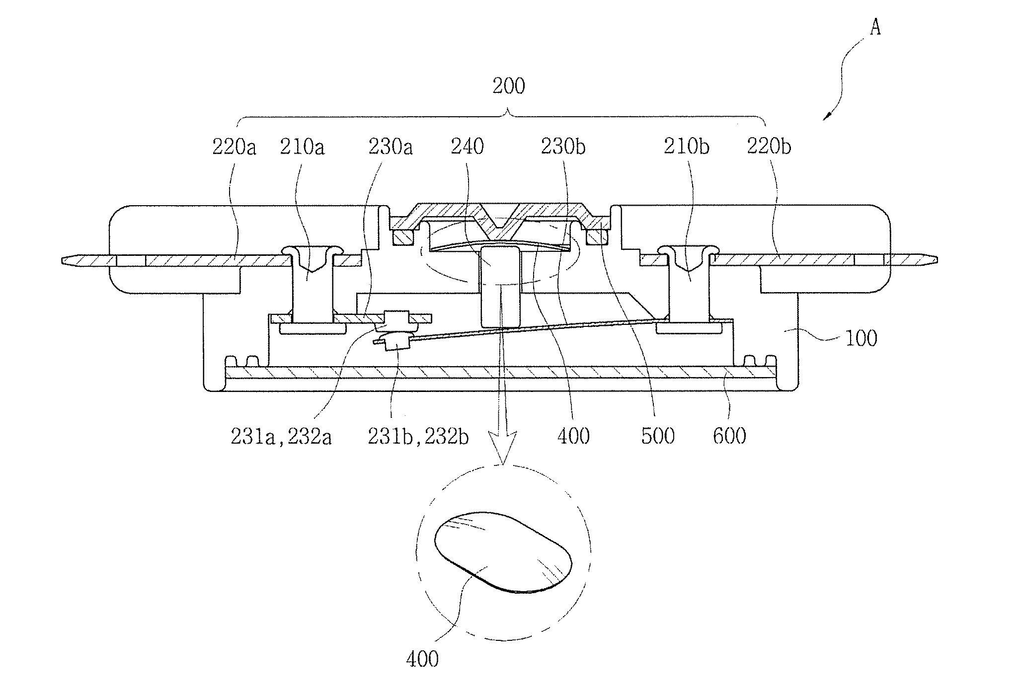
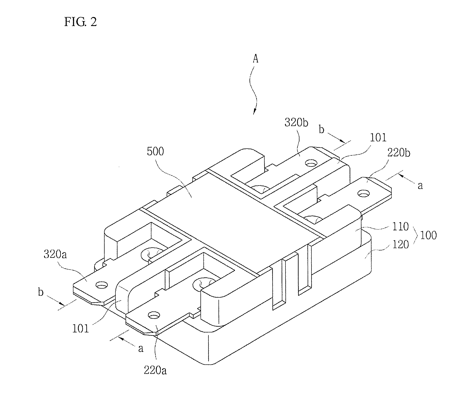
[0061]FIG. 2 is a perspective view illustrating a thermostat according to the first embodiment of the present invention. FIG. 3 is a sectional view taken along line a-a of FIG. 2. FIG. 4 is a sectional view taken along line b-b of FIG. 2. FIGS. 5A and 5B are plan views illustrating a fixed plate and a movable plate of FIG. 2.

[0062]As illustrated in FIGS. 2 to 5, the thermostat A according to the first embodiment of the present invention includes a housing 100, first and second switching sections 200 and 300 installed within the housing 100, and bimetals 400 installed within the housing 100 to electrically insulate the first and second switching sections 200 and 300 at a predetermined temperature, and upper and lower caps 500 and 600 covering upper and lower opened ends of the housing 100.

[0063]First, the housing 100 includes an upper body 110 and a lower body 120, and the first and second switching sections 200 and 300, the bimetals 400, and the upper and lower caps 500 and 600 are ...

second embodiment

[0074]FIG. 6 is a bottom perspective view illustrating a thermostat according to the second embodiment of the present invention. FIG. 7 is a perspective view illustrating a thermostat according to the second embodiment of the present invention. FIG. 8 is a sectional view taken along line a-a of FIG. 7. FIG. 9 is a sectional view taken along line b-b of FIG. 7 according to one embodiment of the present invention. FIG. 10 is a sectional view taken along line b-b of FIG. 7 according to another embodiment of the present invention. FIGS. 11A and 11B are plan views illustrating a fixed plate and a movable plate of FIG. 7. FIG. 12 is an exploded perspective view illustrating a thermostat according to another embodiment of the present invention.

[0075]As illustrated in FIGS. 6 to 11, the thermostat A according to the second embodiment of the present invention includes a housing 100, a first switching section 200 installed within the housing 100, and a bimetal 400 installed within the housing...


PUM


Abstract

Disclosed is a thermostat comprising: a housing; first and second switching sections installed within the housing; a bimetal installed within the housing to electrically insulate the first and second switching sections at a predetermined temperature; and upper and lower caps covering upper and lower opened ends of the housing. According to the thermostat, the first and second switching sections are controlled to simultaneously block a plurality of input terminals.

Description

CROSS-REFERENCE TO RELATED APPLICATION[0001]This application claims priority to and the benefit of Korean Patent Application No. 2009-0031125, filed on Apr. 10, 2009 and Korean Patent Application No. 2009-0104447, filed on Oct. 30, 2009 and Korean Patent Application No. 2010-0010242, filed on Feb. 4, 2010, the disclosures of which are incorporated herein by reference in its entirety.BACKGROUND[0002]1. Field of the Invention[0003]The present invention relates to a thermostat, and more particularly to a thermostat that controls an operation of simultaneously blocking a plurality of input terminals and ensures both prevention of overheating and precise control of temperature.[0004]2. Discussion of Related Art[0005]In general, although electrical devices are safely operated by a certain range of currents or within a certain range of temperatures during a normal operation, they may be damaged or cause a fire due to overheating when an over-current is supplied to them or they are overheat...

Claims


Application Information

Patent Timeline
Patent Type & Authority Applications(United States)
IPC IPC(8): H01H37/52
CPCH01H3/001H01H37/002H01H2037/549H01H2001/0005H01H37/5427
Inventor CHUNG, HAEYANG
Owner HANBECTHISTEM
Learn More