

Indoor positioning system and method
a positioning system and indoor technology, applied in the field of positioning, can solve the problems of the inability to use the gps in a portable apparatus, and the inability to accurately determine the position of the gps indoors
- Summary
- Abstract
- Description
- Claims
- Application Information
AI Technical Summary
Problems solved by technology
Method used
Image

Examples
Embodiment Construction
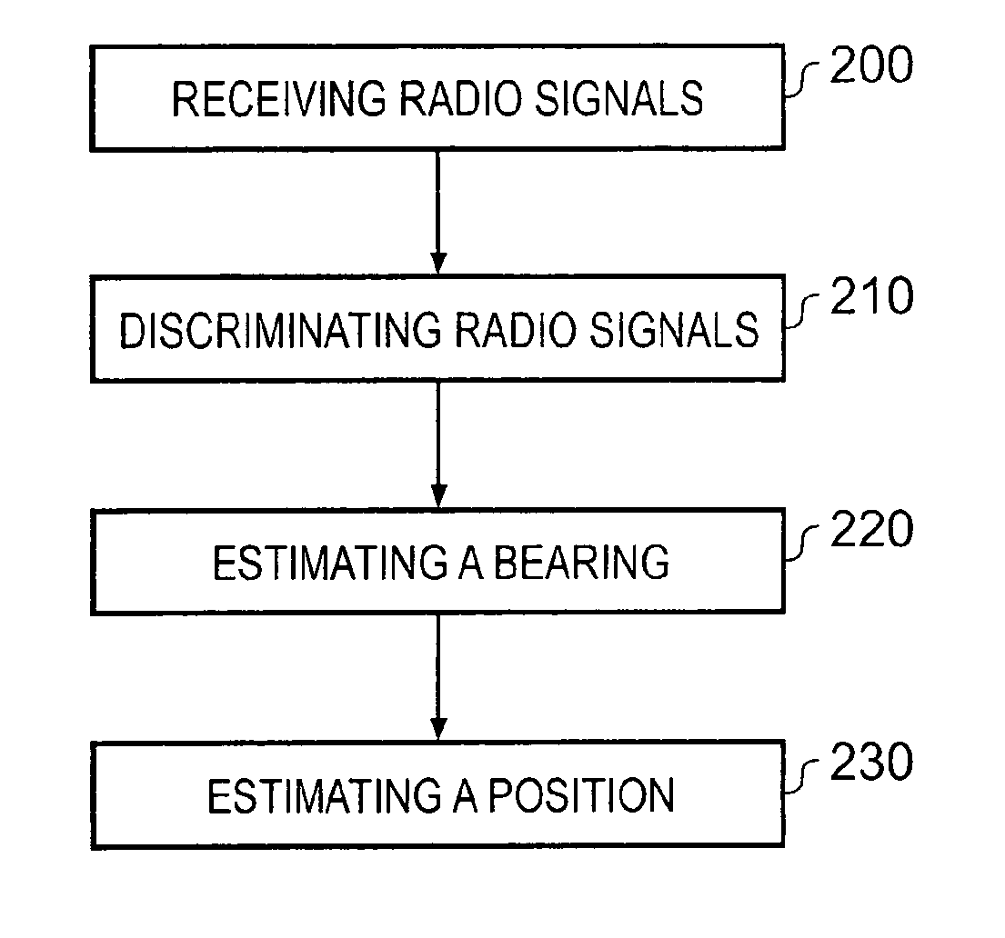
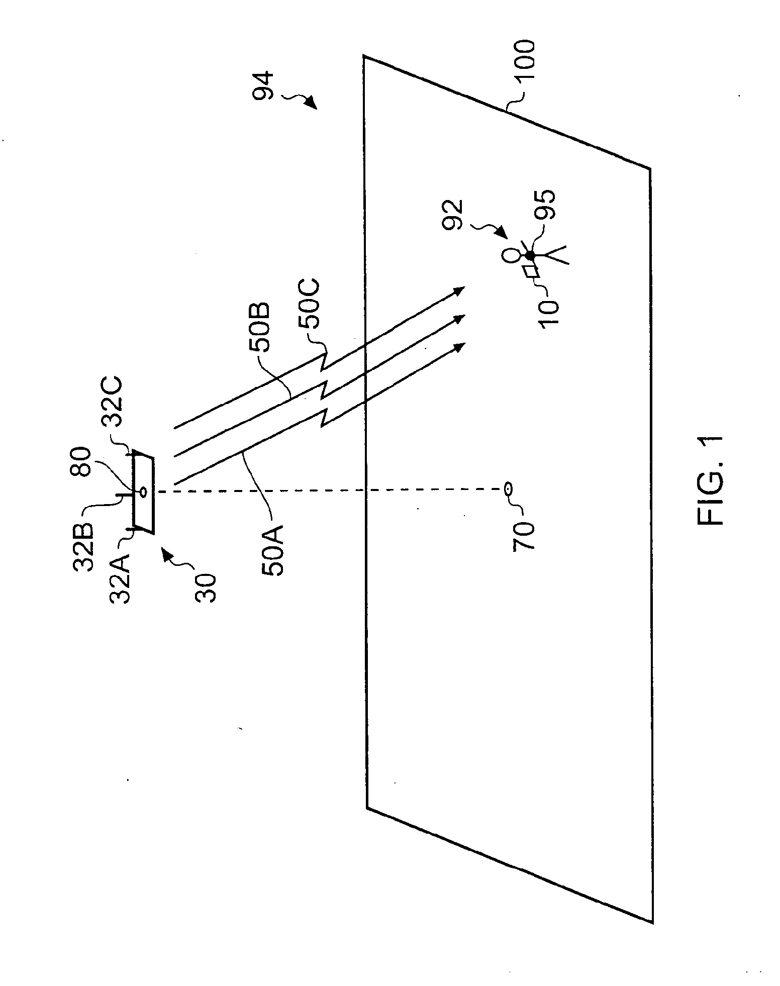
[0004]According to various embodiments of the invention there is provided a method, comprising receiving, at an apparatus radio signals from a first location; discriminating the radio signals, in order to estimate a bearing from the first location; and estimating, using the bearing and constraint information that is independent of the radio signals, a position of the apparatus.
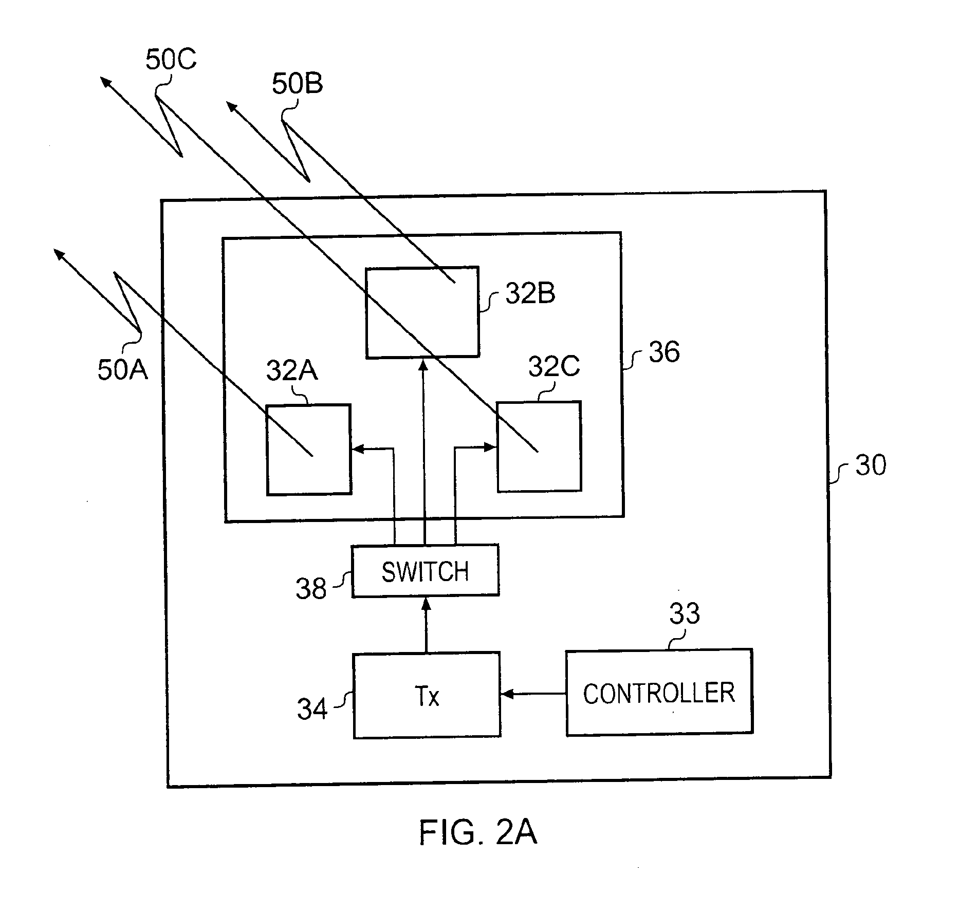
[0005]According to various embodiments of the invention there is provided an apparatus, comprising: a receiver configured to receive radio signals from a first location; processing circuitry configured to discriminate the radio signals, in order to estimate a bearing from the first location, and configured to estimate, using the bearing and constraint information that is independent of the radio signals, a position of the apparatus.
[0006]According to various embodiments of the invention there is provided an apparatus, comprising: means for receiving radio signals from a first location; means for discriminating...
PUM
 Abstract
Description
Claims
Application Information