
Mobile tracking and positioning system

a positioning system and mobile technology, applied in traffic control systems, complex mathematical operations, analog and hybrid computing, etc., can solve the problems of inherently inflexible stationary triangulation systems, system no real precision location or mapping capabilities, and each has its own limitations and drawbacks

Inactive Publication Date: 2001-01-02
ROBERT BRUNO G
View PDF16 Cites 229 Cited by
  • Summary
  • Abstract
  • Description
  • Claims
  • Application Information

AI Technical Summary

Benefits of technology

U.S. Pat. No. 5,345,245 to Ishikawa et al. describes a differential ranging system in which a fixed reference with a known position transmits a corrective factor to a mobile station. The system depends upon a fixed station, hence lacks flexibility and true mobility of all parts of the system. Similarly, U.S. Pat. No. 5,111,209 to Toriyama relates to a satellite-based position determination system that is dependent upon fixed stations. The present invention overcomes these drawbacks by providing true mobile tracking capabilities, without the dependency on a fixed antenna or proximity detectors to locate the target, and wherein each of the mobile tracking stations can precisely locate and map the position of the target. As used herein, the term "mobile", when referring to a tracking and positioning station, refers to a station that has the ability to physically move from one place to another, whether the communication and positioning equipment that constitutes a "station" is installed in a car, an aircraft, a boat, or even carried by a person.
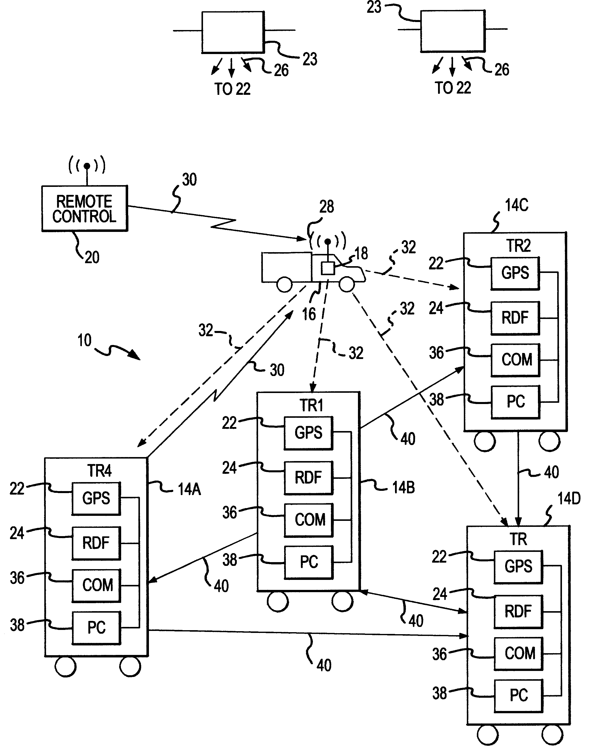
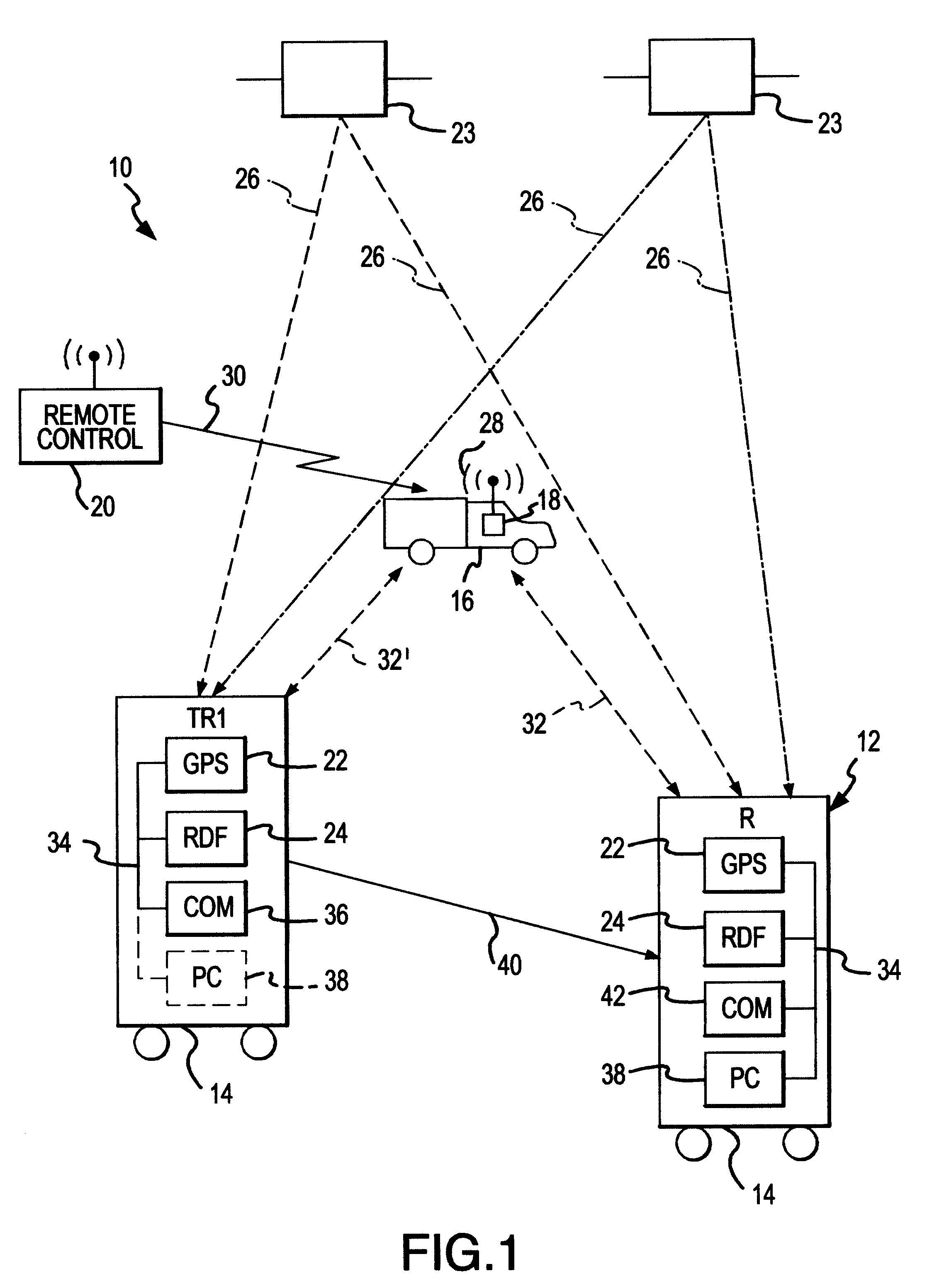
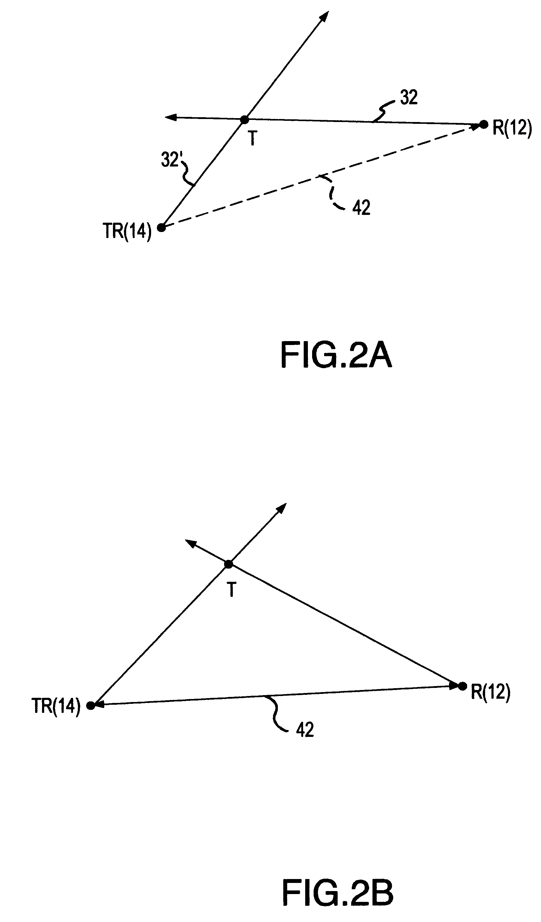
The mobile receive station also has a positioning means for determining the position of the mobile receive station (such as, for example, a GPS receiver), a direction means for receiving the communication signal broadcast from the target and for responsively determining the direction from the mobile receive station to the mobile target (such as an RDF), and a communications system for receiving the transmitted information of the position of the mobile transmit and receive station and the direction of the target to the mobile transmit and receive station. The mobile receive station further includes a computer that triangulates the position of the target from the known position of the mobile transmit and receive station, the known position of the mobile receive station, the known direction of the mobile transmit and receive station to the target, and the known direction of the mobile receive station to the target. By virtue of substantially continuous passing of position and direction information from the mobile transmit and receive station to the mobile receive station, and the simultaneous determination of position and direction information at the mobile receive station, the computer can substantially continuously update the position of the target as the target, the mobile transmit and receive station, and the mobile receive station all move about or above the surface of the earth.

Problems solved by technology

Each has its own limitations and drawbacks.
These systems have no real precision location or mapping capabilities.
Stationary triangulation systems are inherently inflexible, as the position of the triangulation stations is fixed.
The precision in locating the target is not as good, as the homing vehicle does not know its correct position.
The system depends upon a fixed station, hence lacks flexibility and true mobility of all parts of the system.

Method used


Image

  • Mobile tracking and positioning system
  • Mobile tracking and positioning system
  • Mobile tracking and positioning system

Examples


Embodiment Construction

Referring now to FIG. 1, a mobile tracking and positioning system 10 according to a preferred embodiment of the invention is shown in schematic form. The system 10 of FIG. 1 has a mobile receive (R) station 12, a mobile transmit and receive (TR) station 14, and a mobile target 16 to be tracked and located by receive station 12 and transmit and receive station 14. The target 16 has a transmission unit 18 for selectively broadcasting a communication signal 28 (such as a radio signal) in response to the occurrence of a tracking and positioning initiation event. In the case where the target 16 is a vehicle, the initiation event may be the unauthorized movement (e.g., theft) of the vehicle, or it may be the receipt of an activation or initiation signal 30 broadcast from a remote control unit 20 (perhaps a pocket-sized signal transmitter carried by the vehicle's owner) to the target 16 or by a transmit and receive station 14.

The transmit and receive station 14 and the receive station 12 a...


PUM


Abstract

A mobile tracking and positioning system includes a plurality of mobile transmit and receive stations that track a mobile target which emits a radio signal in response to the occurrence of a tracking effort initiation event. The tracking stations have a GPS receiver or like means for determining their position, a radio direction finder responsive to the radio signal that determines the vector to the mobile target, a two-way communications system and a computer. The mobile transmit and receive stations exchange their position and direction to target information via the two-way communications systems, enabling the stations to triangulate the location of the target with their computers.

Description

A. Field of the InventionThe present invention relates generally to the field of systems for tracking and positioning an entity or target, such as a vehicle or person, by surveillance or tracking persons or stations. More particularly, this invention relates to a mobile tracking and positioning system in which a mobile target is tracked by two or more mobile tracking and positioning stations continuously as all the elements of the system (i.e., the target and the tracking and positioning stations) move about or over the surface of the earth. Some typical applications of the invention are in the private security and transportation industries, where the location of a person or vehicle (or persons and fleets of vehicles) are monitored; the recovery of stolen vehicles; and in government applications such as surveillance, intelligence or counterterrorism, where a person or vehicle is positioned and tracked by police or military units.B. Description of Related ArtPrior art tracking and po...

Claims


Application Information

Patent Timeline
Patent Type & Authority Patents(United States)
IPC IPC(8): G08G1/123G08G1/127
CPCG08G1/127G08G1/20
Inventor ROBERT, BRUNO
Owner ROBERT BRUNO G
Learn More