Stand hinge for an electronic device and an electronic device with same

a technology for electronic devices and hinges, which is applied in the direction of portable computer details, electric apparatus casings/cabinets/drawers, instruments, etc., can solve the problems of user inability to maintain such a posture for a long time, large inconvenience in using electronic devices, and limited leaning of electronic devices against a wall, etc., to achieve convenient use, simple operation method, and easy angle adjustment

Inactive Publication Date: 2010-10-14
LAIRD TECH KOREA YH
View PDF12 Cites 66 Cited by
  • Summary
  • Abstract
  • Description
  • Claims
  • Application Information

AI Technical Summary

Benefits of technology

[0026]As described above, the stand hinge for an electronic device of the present invention can be adjusted to different angles since the connecting member and the supporting member are rotated in different directions.
[0027]Further, the connecting member and the supporting member are rotated perpendicularly to each other, thereby providing easy angle adjustment and convenient use.
[0028]Also, the connecting member or the supporting member is semi-automatically rotated, thereby providing a simple operation method and convenient use.
[0029]Additionally, the connecting member or the supporting member is stepwise rotated, thereby allowing the stand hinge to be adjusted at different angles.
[0030]Furthermore, since the friction member is in contact with the stop protrusion while being elastically supported by the elastic member, the connecting member can be semi-automatically rotated.
[0031]Since the stop protrusion is contacted to the friction member to fix the connecting member, the electronic device can stand in a stable manner.

Problems solved by technology

In case the user holds the electronic device in his / her hand, the user cannot maintain such a posture for a long time due to a burden imposed on his / her shoulder or wrist.
Further, leaning the electronic device against a wall is often restricted.
Thus, there is a great inconvenience in using the electronic device.
In addition, there is a drawback in that the electronic device 20 becomes large in volume due to the U-shaped stand 30 attached thereto.

Method used


Image

  • Stand hinge for an electronic device and an electronic device with  same
  • Stand hinge for an electronic device and an electronic device with  same
  • Stand hinge for an electronic device and an electronic device with  same

Examples


Embodiment Construction

[0043]A preferred embodiment of the present invention will now be described in detail with reference to the accompanying drawings.

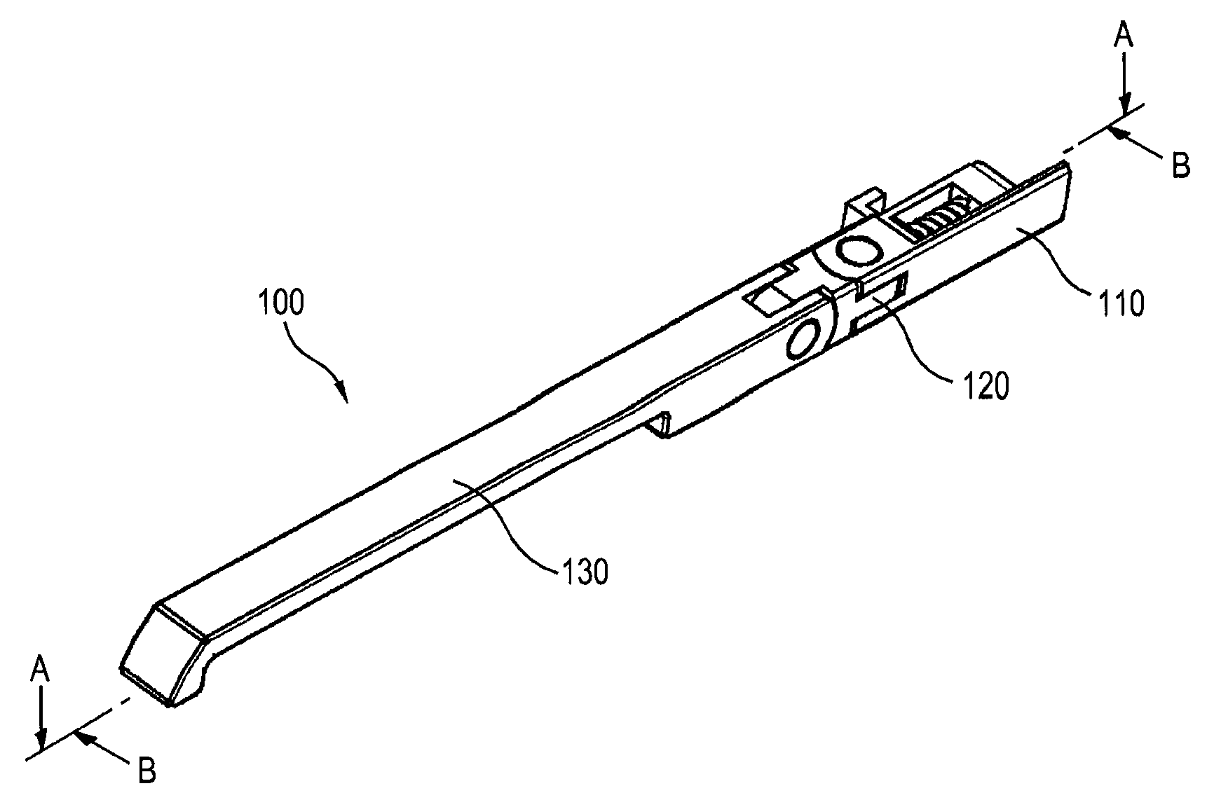
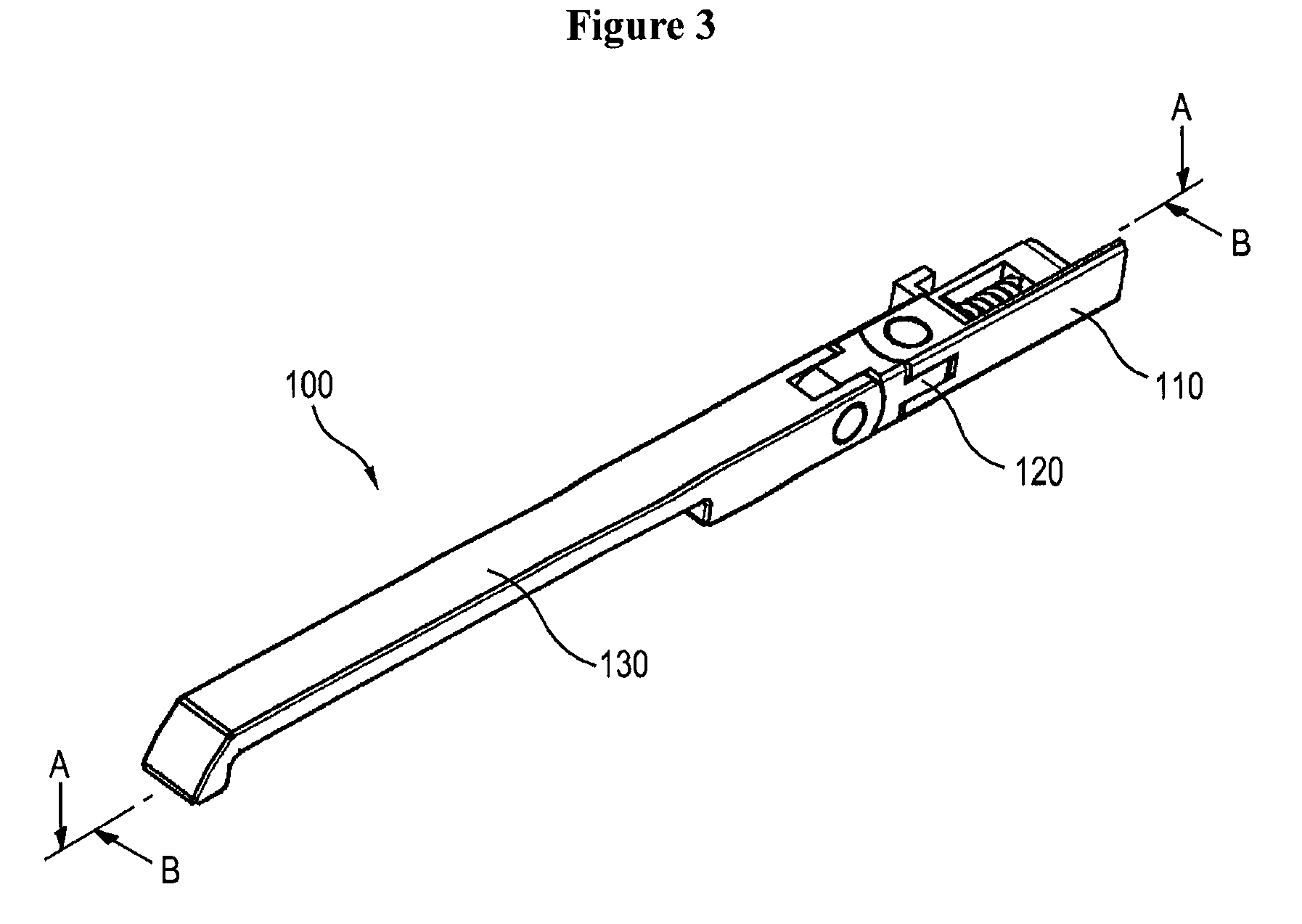
[0044]FIG. 3 is a perspective view of a stand hinge for an electronic device according to one embodiment of the present invention. FIG. 4 is an exploded perspective view of a stand hinge for an electronic device according to one embodiment of the present invention. FIG. 5 is an exploded perspective view of an electronic device with a stand hinge according to one embodiment of the present invention.

[0045]As shown in FIGS. 3 and 4, a stand hinge for an electronic device 100 of the present invention comprises a base 110, a connecting member 120, a supporting member 130, an engaging member 140 and a friction member 150.

[0046]The base 110 has an internal space formed therein. First shaft supports 111 are bilaterally formed at one side of the base. The first shaft supports 111 define a space therebetween, which communicates with the internal space of the base 1...


PUM


Abstract

The present invention provides a stand hinge for an electronic device, which is capable of standing an electronic device at different angles and positions. The present invention further provides an electronic device equipped with the same. The stand hinge of the present invention includes: a connecting member hinge-jointed to an electronic device to rotate in a first direction; and a supporting member for supporting the electronic device against a surface, the supporting member being hinge-jointed to the connecting member to rotate in a second direction different from the first direction.

Description

TECHNICAL FIELD[0001]The present invention generally relates to a stand hinge for an electronic device, and more particularly to a stand hinge for an electronic device that is rotatable at different angles in order to support the same. Further, the present invention relates to an electronic device equipped with the above stand hinge.BACKGROUND ART[0002]Various electronic devices such as DMB (Digital Multimedia Broadcasting) terminals, PMPs (Portable Multimedia Players), portable terminals, etc., which have convenient portability and provide much data by means of an image output device, have been recently introduced in the art.[0003]In particular, the portable terminals have gained great popularity since they provide additional functions (e.g., watching TV or movies or taking photos, etc.) in addition to their inherent mobile communication function.[0004]In order to watch the data from such electronic devices, the image output device of the electronic device must be maintained at app...

Claims


Application Information

Patent Timeline
Patent Type & Authority Applications(United States)
IPC IPC(8): H05K7/00F16M11/06
CPCE05D11/1064E05Y2900/208E05Y2900/606F16M11/10F16M13/005H05K5/0234G06F1/1626G06F1/166H04M1/0214H04M1/04F16M2200/041H04B1/38
Inventor KIM, CHANG SOO
Owner LAIRD TECH KOREA YH
Why Eureka
Try Eureka