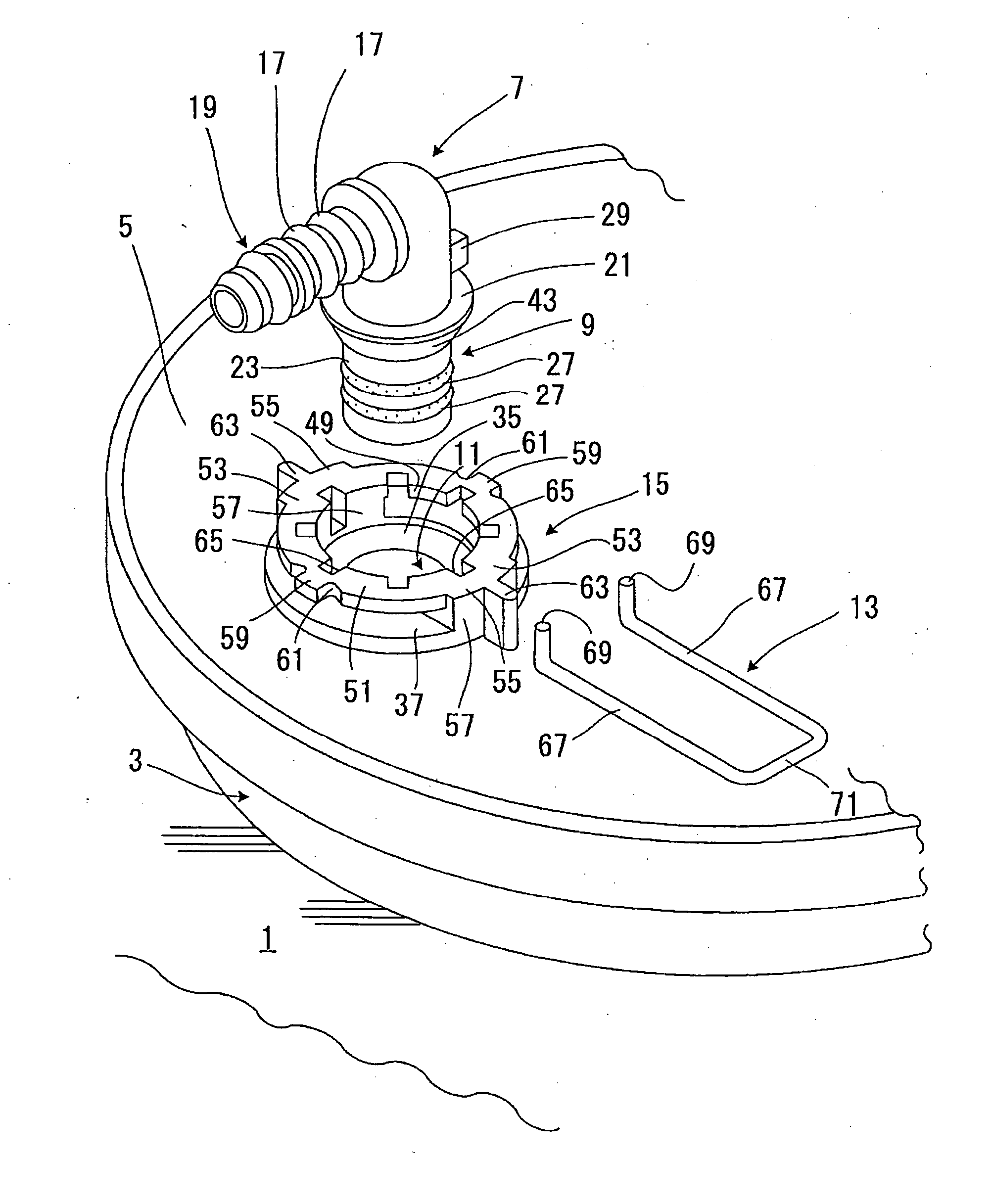
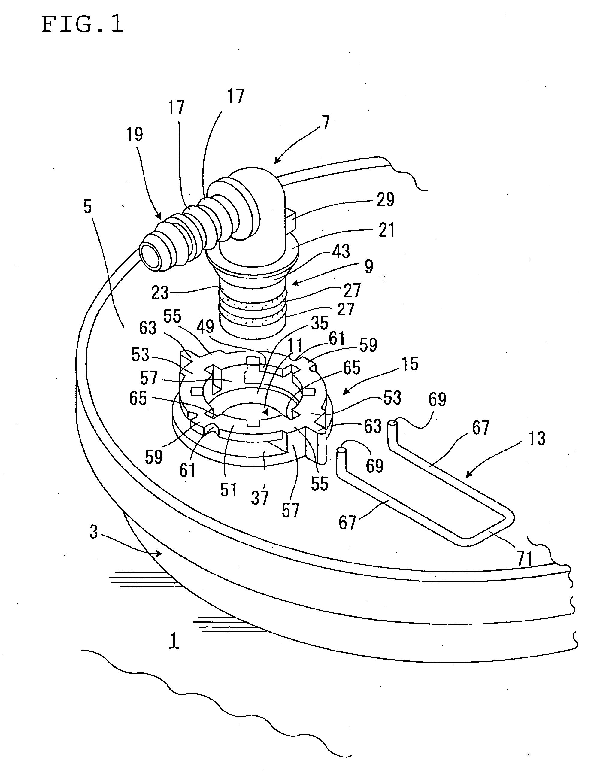
[0010] A connector mounting structure according to the present invention to attain this object includes a structure in which, a fluid piping equipment such as a fuel pump and a
fuel tank is provided with a connection hole, a retainer (for example, in a horseshoe, or approximately
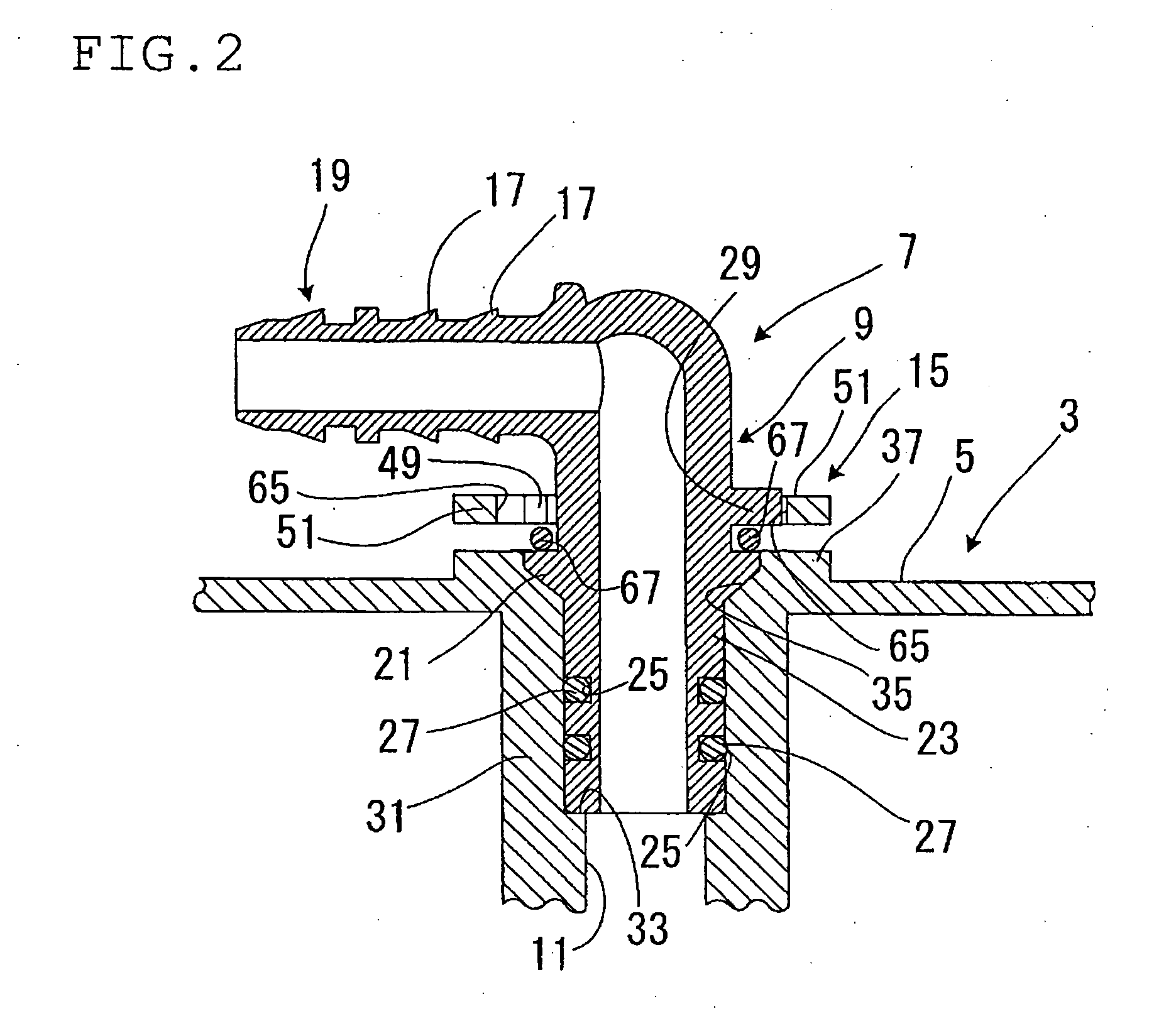
horseshoe shape) is held by a retainer holding portion formed in a vicinity of an opening of the connection hole, a connector is inserted into (for example, plugged in) the connection hole and prevented from dropping out via the retainer to thereby be mounted to the fluid piping equipment. The connector includes: a connecting portion having a cylindrical seal portion (for example, the other end portion in an axial direction) which is inserted into (for example, plugged in) the connection hole and sealed with respect to the connection hole by a seal member, and a
flange stop portion formed on one end in an axial direction of the seal portion and engaged with the retainer in locked relation, a tube fitting portion (widely including a fitting portion of a tubular body for a fluid such as a tube and a hose) formed on one end in the axial direction of the connecting portion in a bending state. A positioning means is disposed between the connecting portion of the connector and the fluid piping equipment. The positioning means has a first engaging portion provided in the connecting portion of the connector and a second engaging portion provided in the fluid piping equipment. The positioning means is to position the connector or the connecting portion of the connector in a circumferential direction so as not to rotate relative to the connection hole by engaging the first engaging portion and the second engaging portion in the circumferential direction. The positioning means has a mounting angle adjusting function capable of positioning the connecting portion in the circumferential direction selectively at any one of a number of mounting angular positions (mounting angular positions in the circumferential direction) relative to the connection hole. An annular surface on the other end in the axial direction of the stop portion is formed in a taper shape tapered toward the other end in the axial direction. Owing to the mounting angle adjusting function, it becomes possible to position the connecting portion in a circumferential direction, for example, respectively at a number of mounting angular positions of three positions or more, or for example, respectively at a number of mounting angular positions of four, five, six positions or more. The connecting portion or the seal portion of the connector may be inserted to be connected to an annular connection hole. Besides, the first engaging portion and the second engaging portion are engaged in the circumferential direction, for example, in response to
insertion of the connecting portion or the seal portion of the connector into the connection hole.
[0012] In the present invention, the retainer held by the retainer holding portion is engaged with the
flange stop portion in locked relation, and thereby, the connector of which connecting portion is inserted into the connection hole is prevented from dropping out relative to the fluid piping equipment. The stop portion is formed, for example, to have a larger outside
diameter (larger outer
diameter) than the seal portion. The retainer is formed, for example, in a
horseshoe shape or approximately
horseshoe shape to have a pair of engaging arms. However, if the annular surface on the other end in the axial direction of the stop portion is formed in a taper shape tapered toward the other end in the axial direction, it becomes possible to have a constitution in which the retainer or the engaging arms may not becomes an intervention for the
insertion of the connecting portion or the seal portion into the connection hole, even if the retainer is held in the retainer holding portion in advance so that, for example, the engaging arms may position in a passage of the stop portion. The connecting portion or the seal portion of the connector is, for example, inserted into the connection hole passing between the pair of engaging arms of the retainer. The annular surface on the other end in the axial direction of the stop portion passes between the engaging arms, for example, so as to press to widen an interval of the pair of the engaging arms, when the connecting portion or the seal portion is inserted into the connection hole. The retainer constitutes a stop structure by being positioning, for example, between the stop portion and the retainer holding portion. The retainer is, for example, held by the retainer holding portion so as not to move in a direction in which the connector is dropped out of the connection hole.
[0013] It is possible to form the pair of the engaging arms of the retainer so as to be snap engaged with the annular surface on one end in the axial direction of the stop portion when the stop portion passes through the engaging arms, to secure an easy and certain stop function of the connector. Further, it is effective that the seal portion or the seal member has a smaller outside
diameter than the interval between the pair of engaging arms of the retainer (the interval when a force to press to widen does not act).
[0015] The retainer holding portion can be formed in an annular body or approximately annular body with a through-hole. Besides, it can be constituted so that the seal portion and the stop portion pass inside of the retainer holding portion (through hole) in the annular body or approximately annular body, when the seal portion is inserted into the connection hole. In case of such a constitution, it is preferable that the second engaging portion, engaging with the first engaging portion provided in the outer periphery of the connecting portion of the connector, is provided in the through hole of the retainer holding portion so that the inserting connection operation of the connector becomes easy. Bedsides, it is effective that the first engaging portion is provided in the outer periphery of the connecting portion, and on one end in the axial direction with respect to the stop portion.
[0016] To secure a certain rotation stop function or anti-
rotation function with an easy constitution, one of the first engaging portion and the second engaging portion is formed as an engaging protruding portion, and the other is formed as an engaging recessed portion capable of fitting on the engaging protruding portion. Namely, it is possible that the first engaging portion is made to be the engaging protruding portion or the engaging recessed portion, and the second engaging portion is made to be the engaging recessed portion or the engaging protruding portion fitting to this first engaging portion to engage therewith in the circumferential direction. Besides, the engaging recessed portions are arranged, for example, in an annular state or in a circular state, and provided more than the number of the engaging protruding portion (one or more), and thereby the mounting angle adjusting function can be constituted. For example, the first engaging portion is set to be the engaging protruding portion, the second engaging portion is set to be the engaging recessed portion fitting on this engaging protruding portion to engage therewith in the circumferential direction, and the engaging recessed portions are provided more than the number of the engaging protruding portions along the circumferential direction in the through hole of the retainer holding portion, and then, a mounting angle adjustment of the tube fitting portion can be performed easily by selecting the engaging recessed portion with which the engaging protruding portion is fitted to be engaged. Incidentally, for example, when a plurality of the engaging protruding portions are arranged, equally spaced in the circumferential direction, the number of the engaging recessed portion may be equal to or more than the number of the engaging protruding portions. The mounting angle of the tube fitting portion can be adjusted effectively with the constitution as stated here. The number of the engaging recessed portion may be equal to or more than the number of the engaging protruding portion.
[0017] According to the connector fixing structure of the present invention, it is possible to position the tube fitting portion extending in an appropriate direction when the connector is mounted, and a complex arranging operation of the retainer becomes unnecessary.

