Biased palatal bone expander

a palatal bone and expander technology, applied in the field of orthodontic appliances, can solve the problem that the mouthpieces do not yet provide expansive lateral forces

Active Publication Date: 2010-10-14
WILLIAMS MICHAEL O
View PDF6 Cites 6 Cited by
  • Summary
  • Abstract
  • Description
  • Claims
  • Application Information

AI Technical Summary

Problems solved by technology

Aligning teeth well along an arc, the mouth pieces do not yet provide expansive lateral forces to widen a jaw or alternatively to contract a jaw.

Method used


Image

  • Biased palatal bone expander
  • Biased palatal bone expander
  • Biased palatal bone expander

Examples


Embodiment Construction

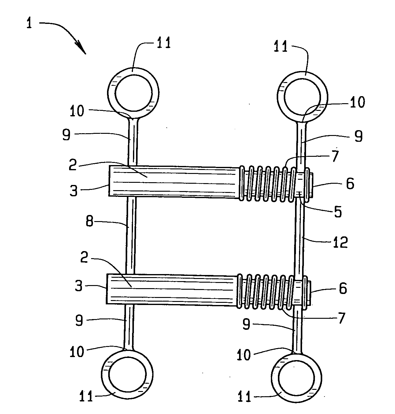
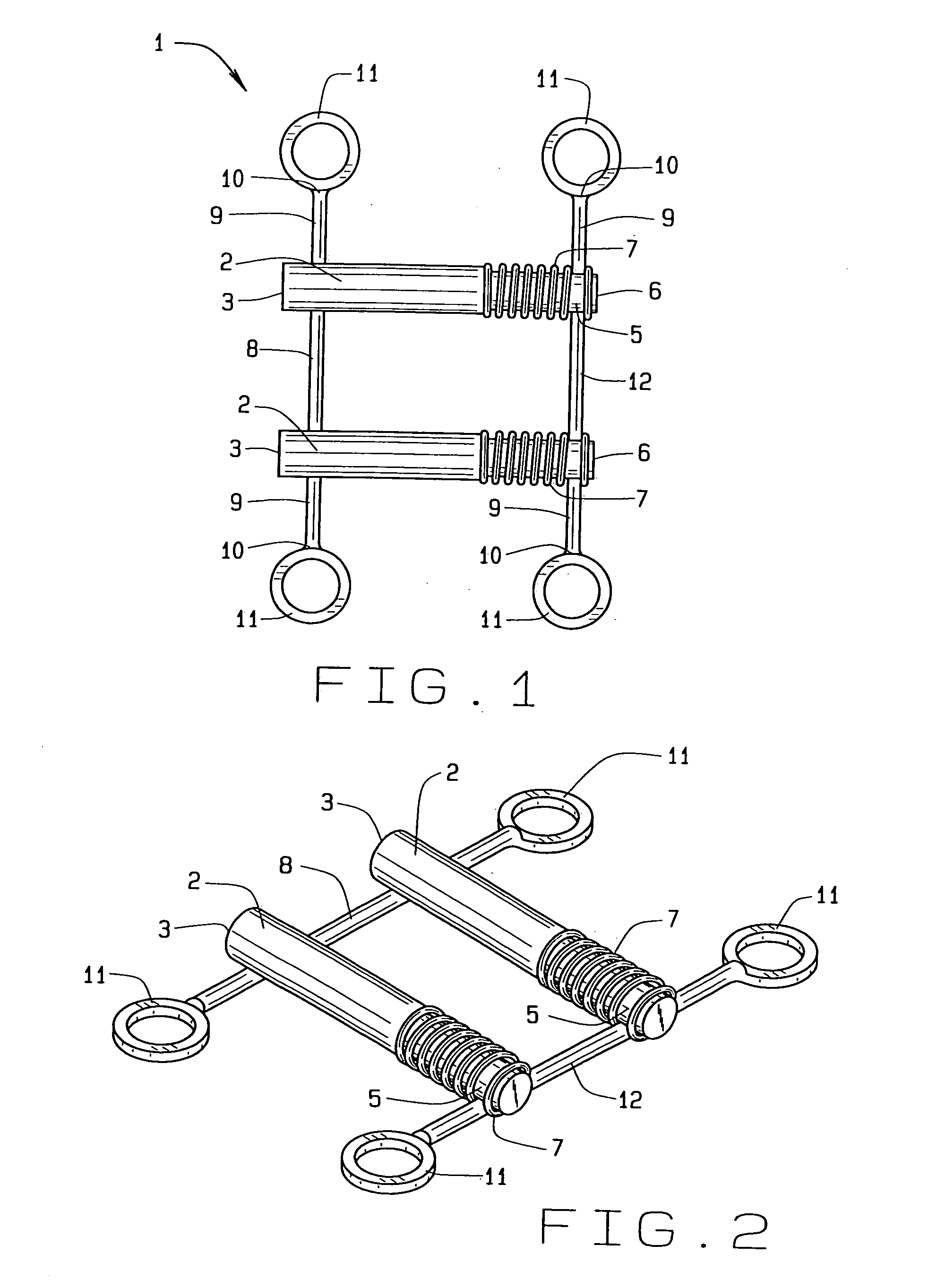
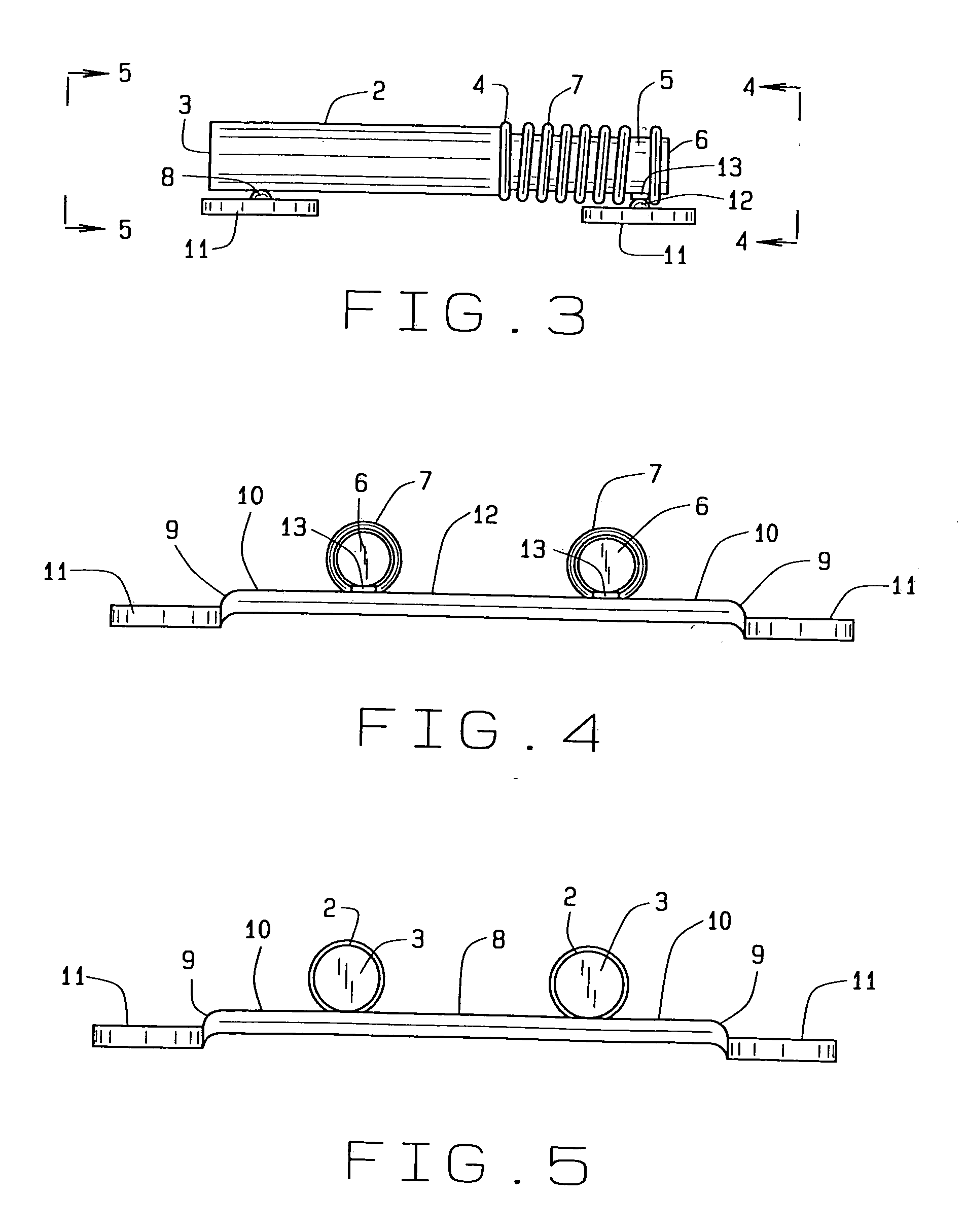
[0027]In referring to the drawings, FIG. 1 shows the present invention before installation in the mouth of a patient to improve various skeletal jaw conditions in people of various ages. The biased palatal expander device of the present invention 1 has a pair of expansion assemblies beginning with tubes 2, generally cylindrical and hollow, mutually parallel and spaced apart. Each tube has two opposite ends with one end having a base 3 and the other end 4 being open. Extending away from the base, the tube has a wall 2a having a thickness, visible at the open end 4.

[0028]From the open end 4, a rod 5 extends outwardly from the tube generally opposite the base. The rod has a cylindrical shape of lesser diameter than the tube and telescopes from within the tube 2 from the open end 4. The rod has a fixed end 6 generally opposite the tube and a free end, not shown, locating within the tube. The rod has sufficient length leaving a portion within the tube to prevent the rod from falling out ...


PUM


Abstract

A biased palatal bone expander attaches directly to the palatal bone in the roof of the mouth of a patient. The expander has dual, biased, mutually parallel rods. The rods extend from coaxial tubes and have coaxial springs. The expansion of the springs urges the rod outwardly from the center of the expander thus widening the maxillary arch incrementally without a connection upon the teeth. The tubes and rods each attach to two mutually parallel bars perpendicular to the rods. Each bar has two opposite ends with an eyelet upon each end. The eyelets receive screws for securing the expander to a patient. Additionally, the appliance may include a thermoformed shell that a surgeon or orthodontist uses to guide positioning the appliance for installation.

Description

CROSS REFERENCE TO RELATED APPLICATION[0001]This application claims priority to the non-provisional patent application having Ser. No. 12 / 006,505, which was filed on Jan. 3, 2008, and claims priority to the non-provisional application for patent Ser. No. 11 / 480,681, filed Jul. 1, 2006 which claims priority to the non-provisional application for patent Ser. No. 10 / 439,638, filed May, 16, 2003, now U.S. Pat. No. 7,094,051, which is commonly owned by the same inventor, and which is a continuation-in-part of application Ser. No. 10 / 186,604, filed Jul. 2, 2002, now U.S. Pat. No. 6,877,982, which is a continuation-in-part of application Ser. No. 09 / 975,633, filed Oct. 12, 2001, now U.S. Pat. No. 6,719,557, and which is a continuation-in-part of application Ser. No. 09 / 750,527, filed Dec. 29, 2000, now U.S. Pat. No. 6,520,772, which is a continuation-in-part of application Ser. No. 09 / 598,766, filed Jun. 22, 2000, now U.S. Pat. No. 6,402,510, which is a continuation-in-part of application ...

Claims


Application Information

Patent Timeline
Patent Type & Authority Applications(United States)
IPC IPC(8): A61C7/10
CPCA61C7/10
Inventor WILLIAMS, MICHAEL O.
Owner WILLIAMS MICHAEL O
Why Eureka
Try Eureka