Supercharge Your Innovation With Domain-Expert AI Agents!

Cyclone Chamber with Vortex Shield

a vacuum cleaner and vortex shield technology, applied in the direction of auxillary pretreatment, cleaning filter means, separation processes, etc., can solve the problems of reducing the performance of the vacuum cleaner, tend to flow,

Inactive Publication Date: 2010-10-21
PRIME SOURCING
View PDF33 Cites 3 Cited by
  • Summary
  • Abstract
  • Description
  • Claims
  • Application Information

AI Technical Summary

Problems solved by technology

A problem with such systems is that large but light weight particles, fibres, hair and the like tend to flow to the exit tube.
These methods provide a barrier for the fibres and hair to accumulate and subsequently reduced the performance of the vacuum cleaner.

Method used


Image

  • Cyclone Chamber with Vortex Shield
  • Cyclone Chamber with Vortex Shield

Examples


Embodiment Construction

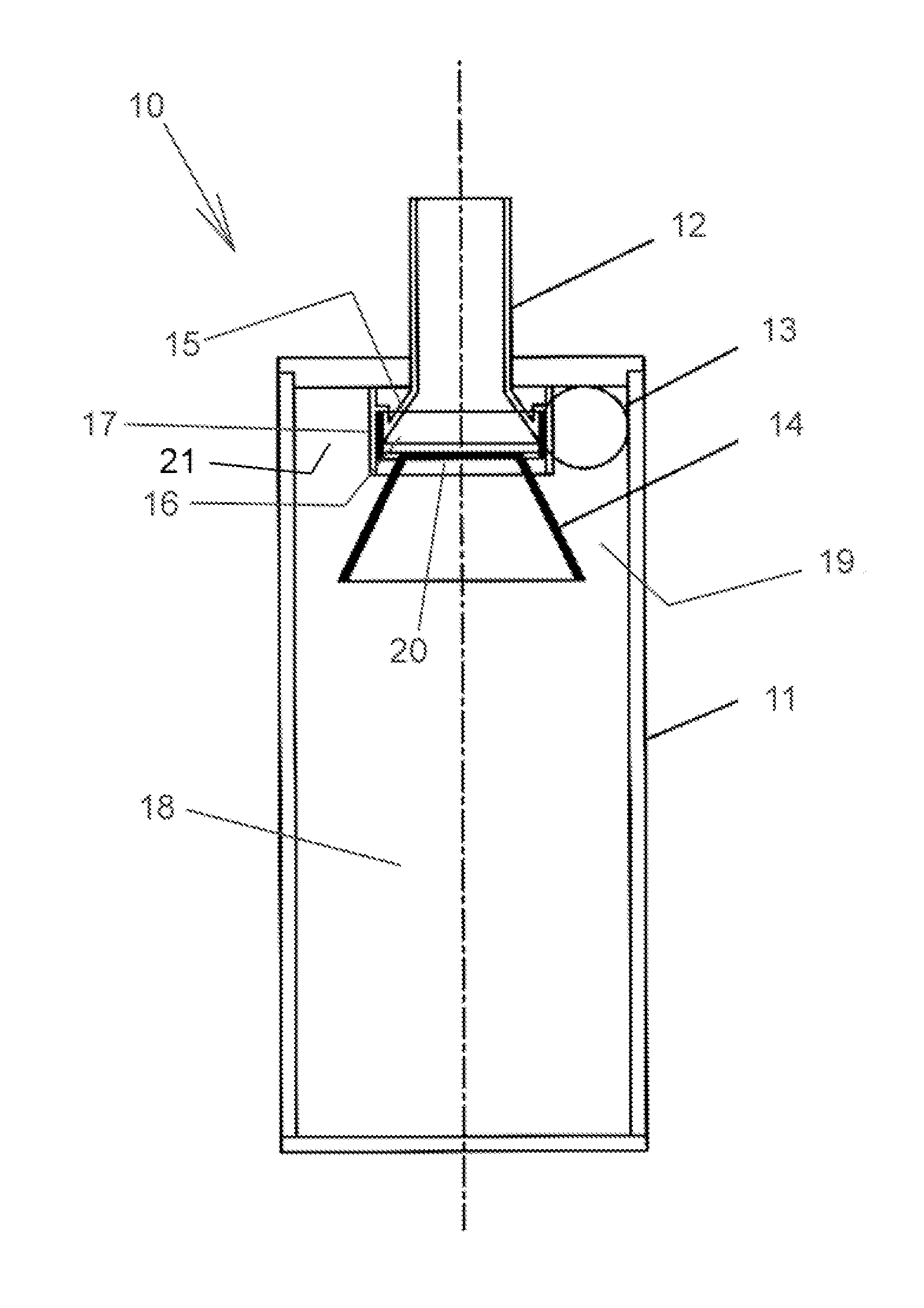
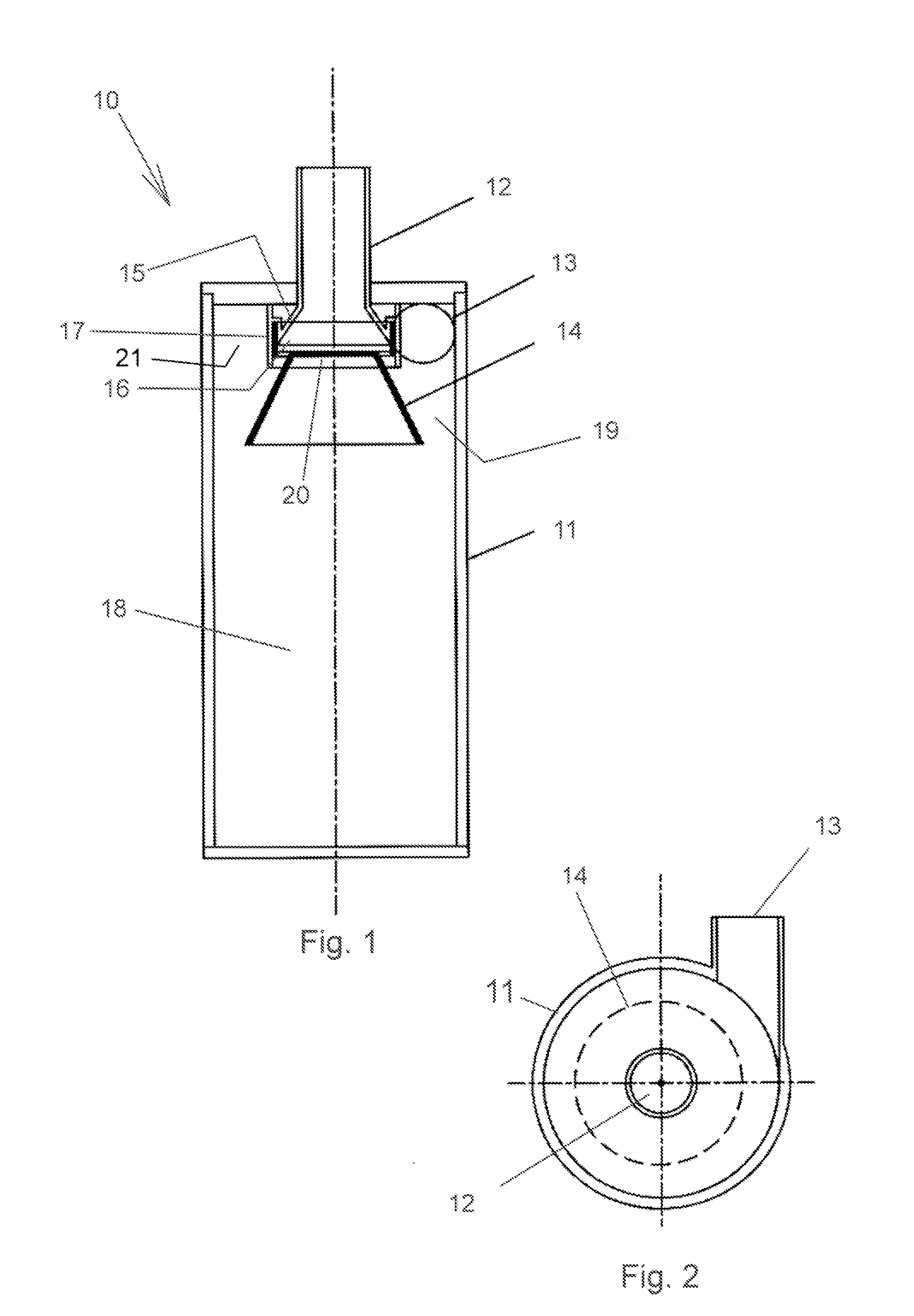
[0017]In the accompanying drawings there is depicted schematically a cyclone 10 which would typically be used as the primary cyclone of a multi-cyclone vacuum cleaner in which a secondary cyclone or cyclones are situated downstream.

[0018]The cyclone 10 comprises a cylindrical wall 11 defining a chamber 18 for receiving the dust, fluff and / or other debris.

[0019]An inlet port 13 extends tangentially of the wall 11. An air exit tube 12 extends axially into the top of the cyclone 10. Low pressure in the exit tube 12 caused by a downstream pump induces low pressure in the chamber 18 which causes air to be drawn in via inlet port 13.

[0020]The exit tube 12 includes a flared opening 15 surrounded by a cylindrical face / frame 17. The upper portion of the chamber wall 11 and the cylindrical face 17 define an annulus 21 into which air from the inlet port 13 is received to form a clockwise rotating cyclonic airflow within the chamber 18. Of course, if the inlet tube were configured differently, ...


PUM

PropertyMeasurementUnit
weightaaaaaaaaaa
pressureaaaaaaaaaa
areaaaaaaaaaaa

Abstract

A cyclone chamber for a vacuum cleaner includes a cylindrical wall defining an internal cavity. An inlet port extends tangentially from the wall such that air entering the cavity via the inlet port causes a cyclonic flow to develop within the chamber. An exit tube extends axially from the chamber and has a flared opening presented into the chamber. A vortex shield is centred axially within the chamber adjacent to the opening and extends radially from the opening toward the wall. The vortex shield forms a barrier to prevent in the most part, large but light weight particles, carpet fibres and the like from escaping into the exit tube.

Description

BACKGROUND OF THE INVENTION[0001]The present invention relates to vacuum cleaner cyclones. More particularly, although not exclusively, the invention relates to a cyclonic chamber for a vacuum cleaner having special internal features for preventing in the most part, large but light weight particles, carpet fibres and the like from escaping through the exit tube.[0002]Known in the art are multi-cyclone vacuum cleaning systems in which a primary cyclone chamber is designed to extract large dust, debris and / or fluff particles entrained in the vacuumed air stream. The primary cyclone feeds a downstream secondary cyclone or cyclones designed for extracting finer particles from the airflow.[0003]A problem with such systems is that large but light weight particles, fibres, hair and the like tend to flow to the exit tube. To prevent the debris from exiting the chamber, common methods such as fine mesh screens or filters are used. These methods provide a barrier for the fibres and hair to ac...

Claims


Application Information

Patent Timeline
Patent Type & Authority Applications(United States)
IPC IPC(8): B01D45/16B04C5/103
CPCA47L9/1658B04C5/13B04C5/103Y10S55/03A47L9/16A47L9/1683B04C5/04B04C5/187
Inventor LEE, YIU-MING
Owner PRIME SOURCING
Features
  • R&D
  • Intellectual Property
  • Life Sciences
  • Materials
  • Tech Scout
  • Unparalleled Data Quality
  • Higher Quality Content
  • 60% Fewer Hallucinations
Learn More