
Low lift golf ball

a golf ball and low-lift technology, applied in the field of golf balls, can solve the problems of increasing the total spin of the ball, reducing the overall shot distance, and tendency to “slice” the ball,

Inactive Publication Date: 2010-10-21
AERO X GOLF
View PDF67 Cites 2 Cited by
  • Summary
  • Abstract
  • Description
  • Claims
  • Application Information

AI Technical Summary

Benefits of technology

[0023]According to one aspect, a golf ball having a plurality of dimples formed on its outer surface, the outer surface of the golf ball being divided into plural areas comprising at least two groups of areas, a first group of areas containing a plurality of first dimples and a second group of areas containing a plurality of second dimples, the areas being arranged to form a spherical polyhedron shape, the first and second groups of areas and dimple shapes and dimensions being configured such that the golf ball is spherically symmetrical as defined by the United States Golf Association (USGA) Symmetry Rules and such that the first and second groups of areas produce different aerodynamic effects, and the first dimples being of different dimensions from the second dimples.

Problems solved by technology

For right-handed golfers, particularly higher handicap golfers, a major problem is the tendency to “slice” the ball.
The unintended slice shot penalizes the golfer in two ways: 1) it causes the ball to deviate to the right of the intended flight path and 2) it can reduce the overall shot distance.
A common cause of a sliced shot is the striking of the ball with an open clubface.
In this case, the opening of the clubface also increases the effective loft of the club and thus increases the total spin of the ball.
As a result, all golf balls not conforming to the USGA Symmetry Rule are judged to be non-conforming to the USGA Rules of Golf and are thus not allowed to be used in USGA sanctioned golf competitions.
These golf balls with asymmetric dimples patterns or with manipulated weight distributions may be effective in reducing dispersion caused by a slice shot, but they also have their limitations, most notably the fact that they do not conform with the USGA Rules of Golf and that these balls must be oriented a certain way prior to club impact in order to display their maximum effectiveness.
The method of using a hard cover material or hard boundary layer material or slippery cover will reduce to a small extent the dispersion caused by a slice shot, but often does so at the expense of other desirable properties such as the ball spin rate off of short irons or the higher cost required to produce a multi-piece ball.

Method used


Image

  • Low lift golf ball
  • Low lift golf ball
  • Low lift golf ball

Examples


Embodiment Construction

.”

BRIEF DESCRIPTION OF THE DRAWINGS

[0025]Features, aspects, and embodiments are described in conjunction with the attached drawings, in which:

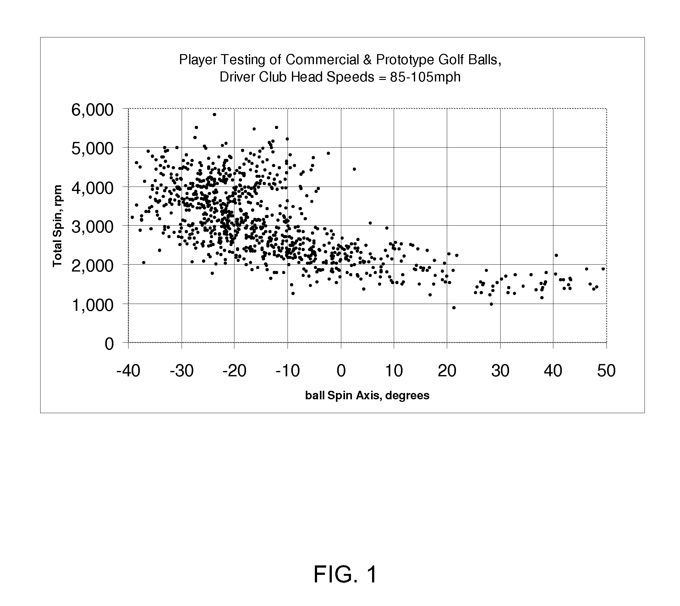
[0026]FIG. 1 is a graph of the total spin rate versus the ball spin axis for various commercial and prototype golf balls hit with a driver at club head speed between 85-105 mph;

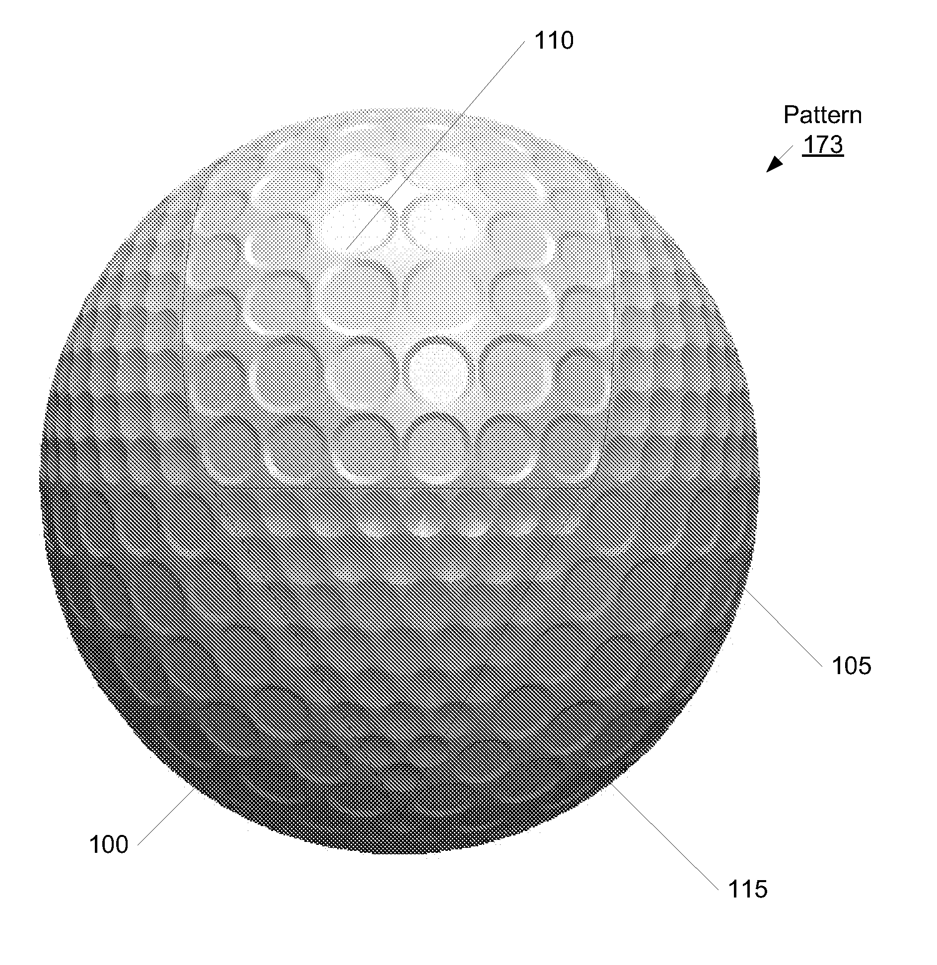
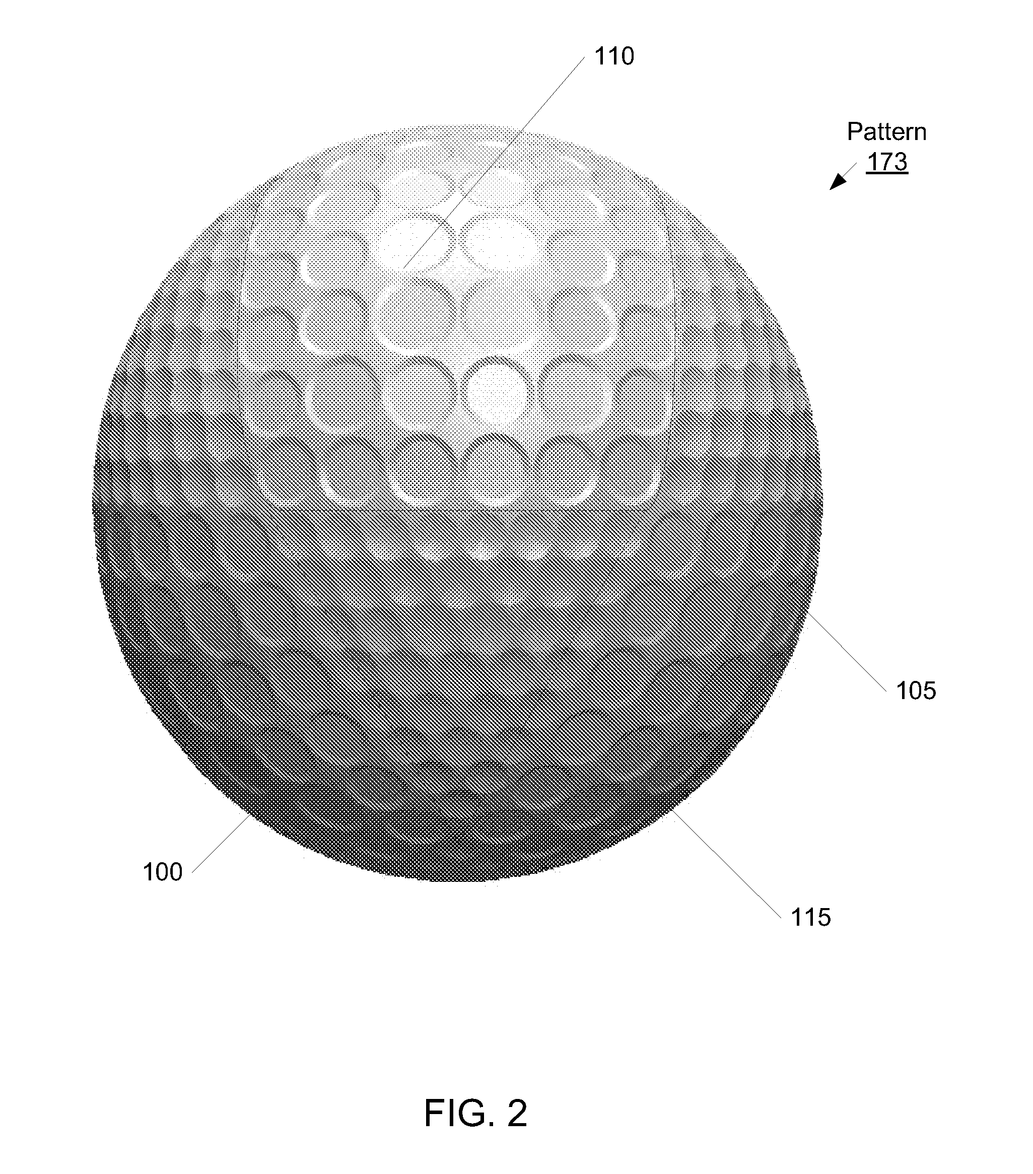
[0027]FIG. 2 is a picture of golf ball with a dimple pattern in accordance with one embodiment;

[0028]FIG. 3 is a top-view schematic diagram of a golf ball with a cuboctahedron pattern in accordance with one embodiment and in the poles-forward-backward (PFB) orientation;

[0029]FIG. 4 is a schematic diagram showing the triangular polar region of another embodiment of the golf ball with a cuboctahedron pattern of FIG. 3;

[0030]FIG. 5 is a graph of the total spin rate and Reynolds number for the TopFlite XL Straight golf ball and a B2 prototype ball, configured in accordance with one embodiment, hit with a driver club using a Golf Labs robot;

[0031]FIG. 6 is a graph or the Lif...


PUM


Abstract

A golf ball having a plurality of dimples formed on its outer surface, the outer surface of the golf ball being divided into plural areas comprising at least two groups of areas, a first group of areas containing a plurality of first dimples and a second group of areas containing a plurality of second dimples, the areas being arranged to form a spherical polyhedron shape, the first and second groups of areas and dimple shapes and dimensions being configured such that the golf ball is spherically symmetrical as defined by the United States Golf Association (USGA) Symmetry Rules and such that the first and second groups of areas produce different aerodynamic effects, and the first dimples being of different dimensions from the second dimples.

Description

RELATED APPLICATIONS INFORMATION[0001]This application claims the benefit under 35 U.S.C. §120 of copending patent application Ser. No. 12 / 757,964 filed Apr. 9, 2010 and entitled “A Low Lift Golf Ball,” which in turn claims the benefit under §119(e) of U.S. Provisional Application Ser. No. 61 / 168,134 filed Apr. 9, 2009 and entitled “Golf Ball With Improved Flight Characteristics,” all of which are incorporated herein by reference in their entirety as if set forth in full.BACKGROUND[0002]1. Technical Field[0003]The embodiments described herein are related to the field of golf balls and, more particularly, to a spherically symmetrical golf ball having a dimple pattern that generates low-lift in order to control dispersion of the golf ball during flight.[0004]2. Related Art[0005]The flight path of a golf ball is determined by many factors. Several of the factors can be controlled to some extent by the golfer, such as the ball's velocity, launch angle, spin rate, and spin axis. Other fa...

Claims


Application Information

Patent Timeline
Patent Type & Authority Applications(United States)
IPC IPC(8): A63B37/14
CPCA63B37/0004A63B37/0006A63B37/0009A63B37/0012A63B37/0096A63B37/0019A63B37/002A63B37/0021A63B37/009A63B37/0018A63B37/14A63B37/12
Inventor FELKER, DAVID L.WINFIELD, DOUGLAS C.LEE, ROCKY
Owner AERO X GOLF
Learn More