Power supply apparatus and power supply method
- Summary
- Abstract
- Description
- Claims
- Application Information
AI Technical Summary
Benefits of technology
Problems solved by technology
Method used
Image

Examples
first embodiment
1. FIRST EMBODIMENT
[0034][1-1. Arrangement of Power Supply System]
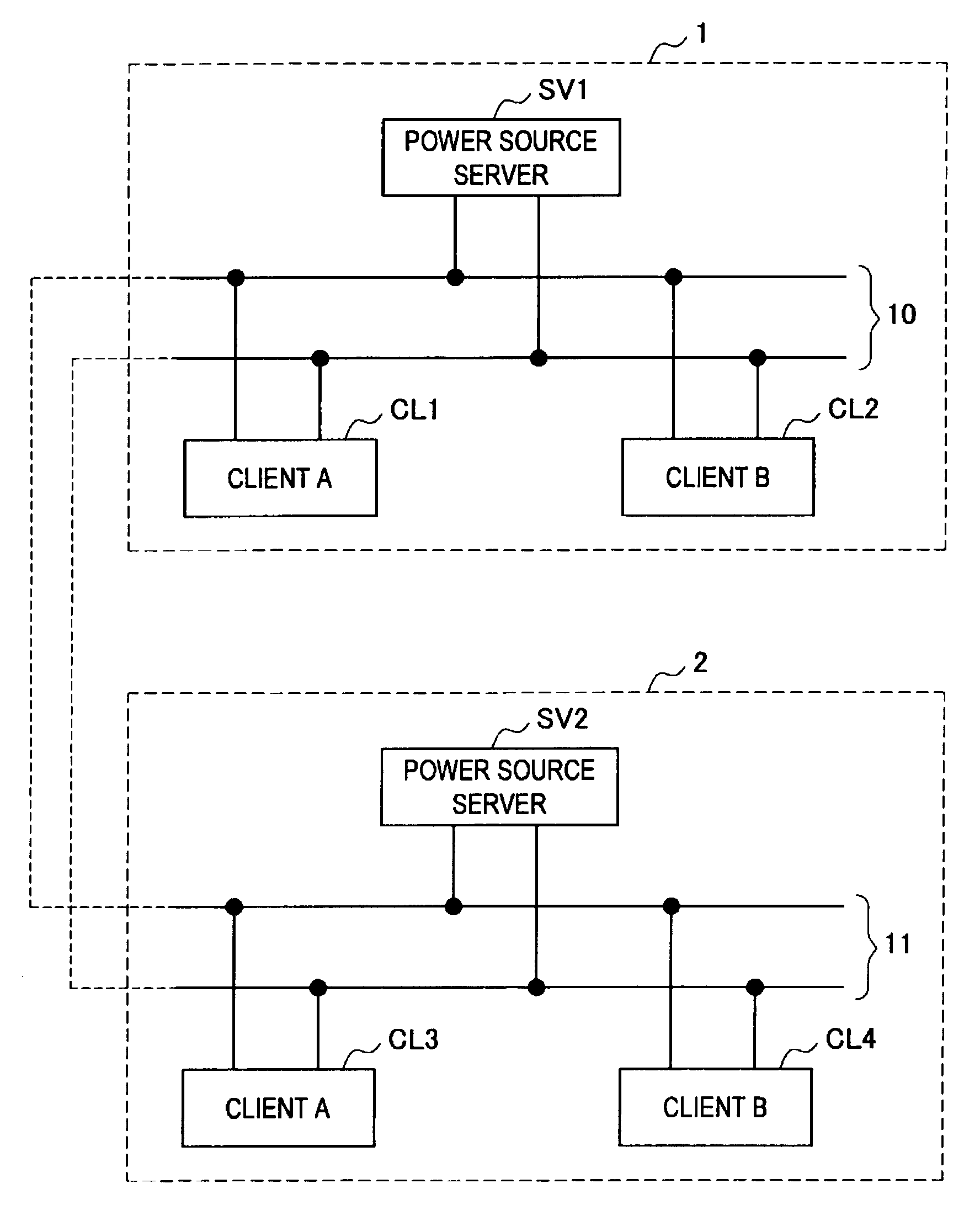
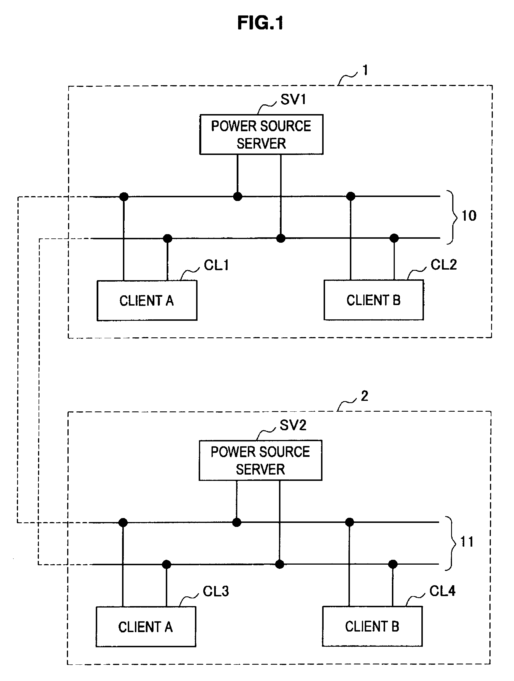
[0035]First of all, the arrangement of a power supply system according to the first embodiment of the present invention will be described. FIG. 1 is an illustration that shows the arrangement of the power supply system according to the first embodiment of the present invention. Now, the arrangement of the power supply system according to the first embodiment of the present invention will be described below with reference to FIG. 1.
[0036]As shown in FIG. 1, the power supply system according to the first embodiment of the present invention includes two power supply systems 1 and 2. The power supply systems include one power source server SV1 or SV2 and clients CL1 and CL2 or CL3 and CL4, respectively. The power source servers 100 and the clients 200 are connected via a bus line 10 or 11.
[0037]The power source servers SV1 and SV2 supply direct-current power to the clients CL1, CL2, CL3, and CL4. Moreover, the power sourc...
second embodiment
2. SECOND EMBODIMENT
[0087]As described above, in the first embodiment of the present invention, multiple power supply apparatuses share one battery, so that multiple power supply systems are connected to each other not for information but for energy. Now, a question arises amongst these power supply apparatuses: which power supply apparatus of the power supply apparatuses sharing a battery should offer a battery? Then, as described below, in the second embodiment of the present invention, the power supply apparatuses, all of which include own batteries, are connected to each other, so that multiple power supply systems can be connected to each other not for information but for energy.
[0088]FIG. 7 is an illustration that shows the arrangements of the power supply apparatuses 200a and 200b according to the second embodiment of the present invention. Now, the arrangements of the power supply apparatuses 200a and 200b according to the second embodiment of the present invention will be d...
third embodiment
3. THIRD EMBODIMENT
[0095]As described above, in the second embodiment of the present invention, the power supply apparatuses, all of which include own batteries, are connected to each other, so that multiple power supply systems can be connected to each other not for information but for energy. Although the power supply apparatuses 200a and 200b shown in FIG. 7 can share with each other the power stored in the batteries 240a and 240b, they do not include any means for informing each other of information of power supplied by each of them. In the third embodiment, power supply apparatuses, such as the power supply apparatuses 200a and 200b shown in FIG. 7, additionally include means for informing each other of information of the power supplied by each of them.
[0096]FIG. 8 is an illustration that shows the arrangement of a power supply apparatus 300a according to the third embodiment of the present invention. Now, the arrangement of the power supply apparatus 300a according to the thir...
PUM
 Abstract
Description
Claims
Application Information
 - R&D Engineer
- R&D Manager
- IP Professional
- Industry Leading Data Capabilities
- Powerful AI technology
- Patent DNA Extraction
Browse by: Latest US Patents, China's latest patents, Technical Efficacy Thesaurus, Application Domain, Technology Topic.
© 2024 PatSnap. All rights reserved.Legal|Privacy policy|Modern Slavery Act Transparency Statement|Sitemap