
Ink jet recording apparatus and ink jet recording method

Inactive Publication Date: 2010-11-04
CANON KK
View PDF14 Cites 1 Cited by
  • Summary
  • Abstract
  • Description
  • Claims
  • Application Information

AI Technical Summary

Benefits of technology

[0019]However, in a case where mask patterns, such as those shown in FIG. 5, are employed, the specific ink (yellow ink) is allowed to be applied only by the nozzles in the region 4, which are used only during the last recording pass among the multiple (four) recording passes in the primary scan direction. That is, even if the portion of an image to be formed, is such a portion of the image that the special ink does not overlap with the other inks (nonspecific inks)

Problems solved by technology

Therefore, the nozzles become unnecessarily uneven in usage frequency, and also, the multiple recording passes become unnecessarily uneven in recording permission ratio.
The unevenness in the nozzle usage frequency and the unevenness in recording permission ratio among the multiple recording passes detract the benefits of the multi-pa

Method used


Image

  • Ink jet recording apparatus and ink jet recording method
  • Ink jet recording apparatus and ink jet recording method
  • Ink jet recording apparatus and ink jet recording method

Examples


Example

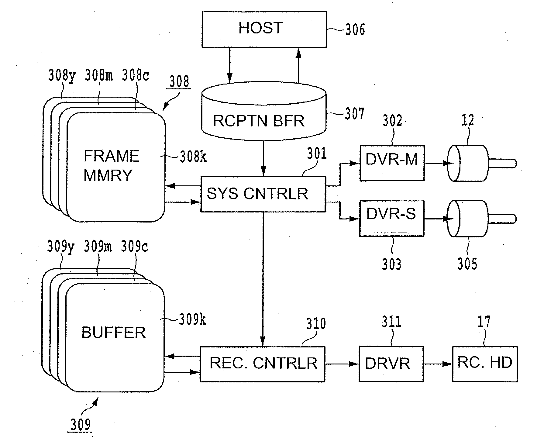
[0120]Also in this embodiment, the same inks as those used in the first embodiment are used by the same ink jet recording apparatus as the one used in the first embodiment and shown in FIGS. 6-8 are used. Further, the image processing steps carried out by the host apparatus in this embodiment are roughly the same as those in the first embodiment, which were described using the flowcharts in FIGS. 9 and 10. However, in this embodiment, the 4-bit data conversion process 108 (step) is not carried out in the host apparatus. Instead, the density data 107 made up of the 8-bit data obtained for each color by the color separation process, and the mask separation parameter MP, are transmitted to the recording apparatus.

[0121]Further, in this embodiment, the recording apparatus does not prepare the binary mask patterns such as those in the first embodiment. Instead, it prepares mask patterns (recording permission ratio determining patterns) which determine only the recording permission ratio ...

Example

EMBODIMENT 3

[0136]Also in this embodiment, the same ink jet recording apparatus shown in FIGS. 6-8, and the same ink, as those used in the above described embodiments, are used. As for the series of image processing steps used in this embodiment, it is roughly the same as that used in the second embodiment. In this embodiment, however, instead of the mask parameter MP in FIG. 10, the intermediary mask selection parameter MP′1104 in FIG. 10, that is, the mask selection parameter prior to the binarization process, is transferred to the recording apparatus. Thus, the recording apparatus in this embodiment receives the density datum 107, which is made up of eight bits per color of unit pixel, and the intermediary mask selection parameter MP′1104, which is made up of five bits, being there capable of having 32 different values, from the host apparatus.

[0137]FIG. 20 is a drawing for describing 32 different mask patterns 0-31 prepared in this embodiment. The mask pattern 0 in the drawing i...

Example

EMBODIMENT 4

[0143]In order to prevent the formation of an image which suffers from the nonuniformity in density, which is attributable to positional registration errors, the second and third embodiments, which adopted the structural arrangement disclosed in Japanese Laid-open Patent Application 2000-103088, binarized the nonbinary (multi-value) density datum after dividing the multiple data, which correspond one for one to multiple recording passes (scans) (which correspond to multiple nozzle groups; multiple regions of nozzle column). However, in case where the binarization process is carried out after the division of the density data into multiple data, there is no complementary positional relationship among the dots recorded during each recording scan, and therefore, there will be unit pixels into which no dot is recorded even if an image to be recorded is a 100% image, and / or unit pixels into which two or more dots are recorded in layers. Japanese Laid-open Patent Application 20...


PUM


Abstract

When recording with the use of a multi-pass recording method, the order in which a specific ink and the other inks are applied in layers is controlled while preventing the multiple recording scans (passes) from becoming unnecessary uneven in terms of the ink recording permission ratio, and also, the ratio with which the specific ink is permitted to be applied to each unit pixel is determined for each recording scan (pass), based on the information (for example, CMYK information, RGB information, etc.) regarding the specific ink and the other inks, which are to be applied to each unit pixel. Therefore, it is possible to change the recording scan(s), to which the application of the specific ink is concentrated, based on the application conditions for the specific ink and the other inks, and therefore, it is possible to change the ratio with which the specific ink is applied before or after the other inks are applied. Therefore, it is possible to control the order in which the specific ink and the other inks are applied in layers.

Description

FIELD OF THE INVENTION AND RELATED ART[0001]The present invention relates to an ink jet recording apparatus which records an image on recording medium while moving its ink applying means (recording head), which is capable of applying multiple kinds of ink, in a manner to scan the recording medium. It also relates to an ink jet recording method.[0002]An ink jet recording apparatus is superior to a recording apparatus of the other type in that it is capable of recording at a higher density and a higher speed, is lower in cost, and is quieter than the recording apparatus of the other type. It has been commercialized in various forms, for example, an outputting device for various apparatuses, a portable printer, etc. In recent years, there have come to be offered various ink jet recording apparatuses capable of forming a color image with the use of multiple inks different in color.[0003]Generally, an ink jet recording apparatus has: a recording means (recording head) which jets ink in r...

Claims


Application Information

Patent Timeline
IPC IPC(8): B41J29/38
CPCB41J19/147
Inventor KANEKO, TAKUMIFUJIMOTO, YASUNORIYANAI, TOMOKAZU
Owner CANON KK
Learn More