Eureka AIR delivers breakthrough ideas for toughest innovation challenges, trusted by R&D personnel around the world.

Light-emitting device and optical transmission unit

Inactive Publication Date: 2005-01-06
FUJIFILM BUSINESS INNOVATION CORP
View PDF20 Cites 0 Cited by
  • Summary
  • Abstract
  • Description
  • Claims
  • Application Information

AI Technical Summary

Benefits of technology

[0013] It is therefore an object of the invention to provide a light-emitting device capable of making up for the lowness of output of each vertical-cavity surface-emitting laser diode (VCSEL) and shortening of the life of the VCSEL if a drive current is increased and an optical transmission unit using the light-emitting device.

Problems solved by technology

However, in the technique disclosed in Document 1, a plurality of face light-emitting laser diodes each having a horizontal resonator, a waveguide, and a diffraction grating need to be disposed so that optical signals emitted from the face light-emitting laser diodes are gathered at one point, and it is hard to manufacture.
The laser diode array disclosed in Document 2 is used to transmit an optical signal by wavelength division multiplexing, and does not solve the problems of low output of VCSEL and shortening the life if the drive current is increased.

Method used


Image

  • Light-emitting device and optical transmission unit
  • Light-emitting device and optical transmission unit
  • Light-emitting device and optical transmission unit

Examples


Embodiment Construction

[0003] 1. Field of the Invention

[0004] This invention relates to a light-emitting device and an optical transmission unit for converting an electric signal into an optical signal and transmitting the optical signal.

[0005] 2. Description of the Related Art

[0006] As a device for converting an electric signal into an optical signal, for example, a vertical-cavity surface-emitting laser diode (VCSEL) is in the actual use.

[0007] The VCSEL has the characteristics of small threshold current as compared with an end surface light-emitting laser diode and being easily put into an array.

[0008] Generally, the VCSEL has the features of low output as compared with a general laser diode and life shortened in proportion to the square or the cube of a current value if a drive current is increased.

[0009] For example, JP-A-7-38205 (Document 1) discloses a technique of generating an optical signal using a plurality of face light-emitting laser diodes.

[0010] However, in the technique disclosed in...


PUM


Abstract

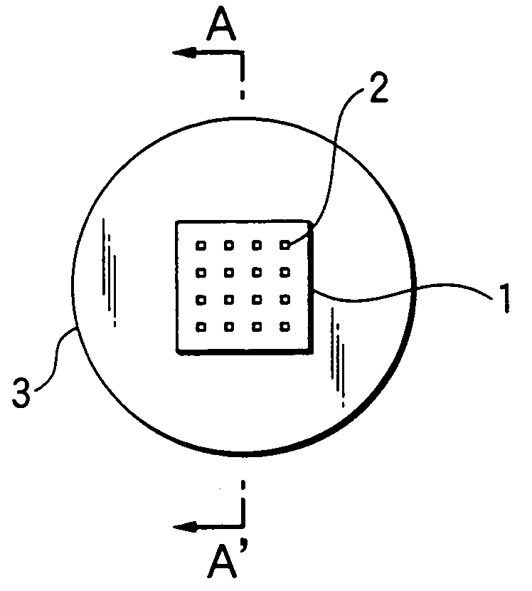
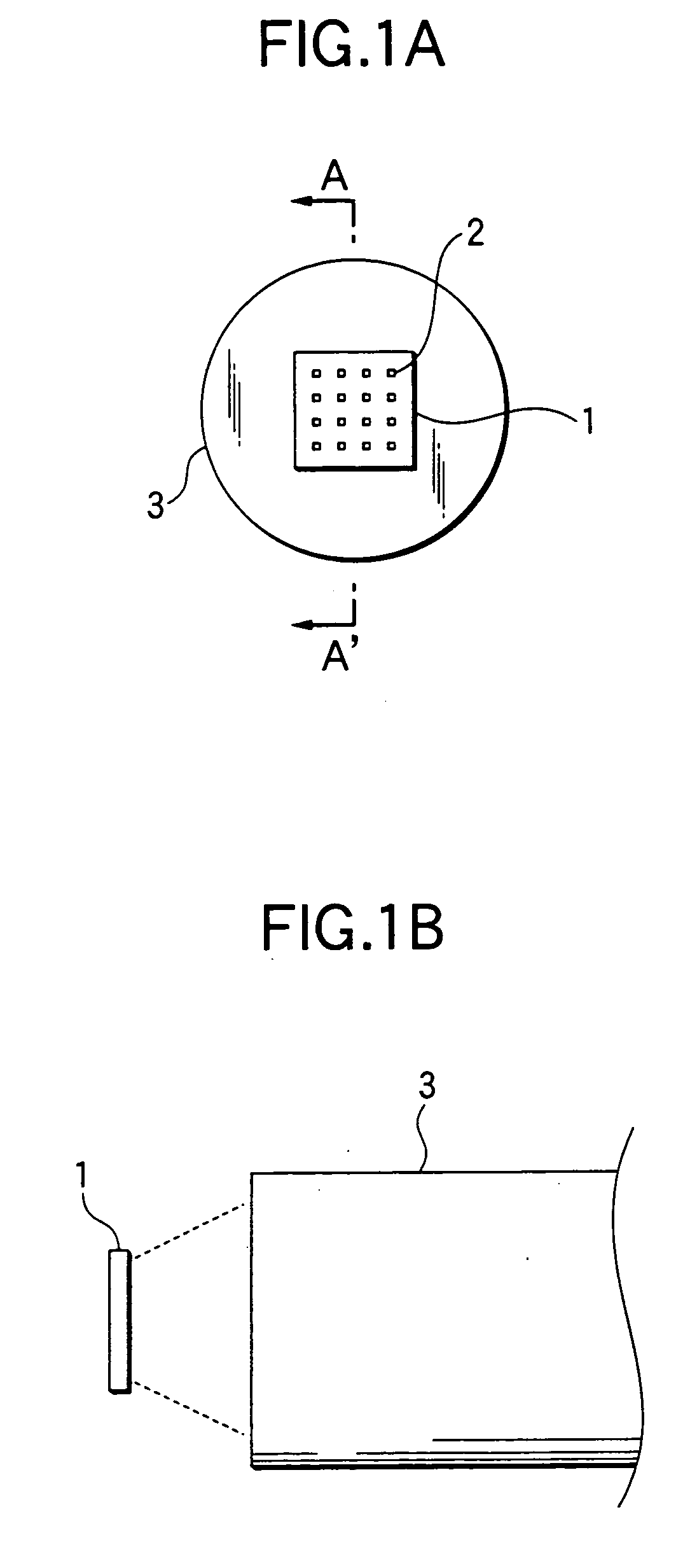
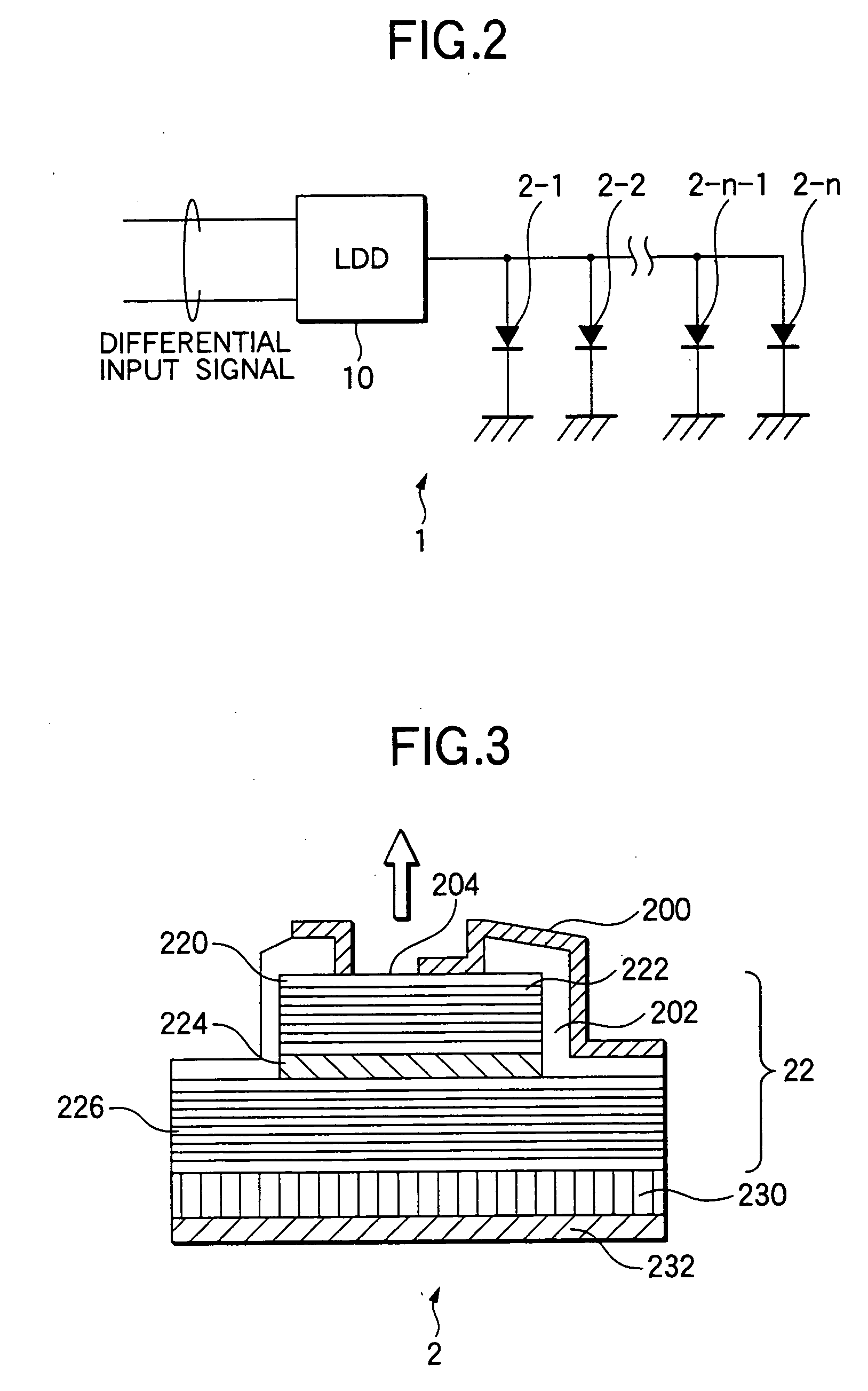
A light-emitting device includes 16 vertical-cavity surface-emitting laser diodes (VCSELs) disposed like a 4×4 grid, for example, in a sufficiently narrower range than the end surface of an optical fiber. The 16 VCSELs disposed in the light-emitting device emit optical signals in the same direction. Since the VCSELs are disposed with a concentration in the sufficiently narrower range than the end surface of the optical fiber as described above, if the optical signals emitted from the VCSELs are spread, almost all optical signals generated by the light-emitting device are incident on the end surface of the optical fiber and are transmitted through the optical fiber.

Description

[0001] This is a Division of application Ser. No. 10 / 292,454 filed Nov. 13, 2002. The entire disclosure of the prior application is hereby incorporated by reference herein in its entirety. [0002] The present disclosure relates to the subject matter contained in Japanese Patent Application No. 2001-348702 filed on Nov. 14, 2001, which is incorporated herein by reference in its entirety.BACKGROUND OF THE INVENTION DETAILED DESCRIPTION OF THE INVENTION [0003] 1. Field of the Invention [0004] This invention relates to a light-emitting device and an optical transmission unit for converting an electric signal into an optical signal and transmitting the optical signal. [0005] 2. Description of the Related Art [0006] As a device for converting an electric signal into an optical signal, for example, a vertical-cavity surface-emitting laser diode (VCSEL) is in the actual use. [0007] The VCSEL has the characteristics of small threshold current as compared with an end surface light-emitting las...

Claims


Application Information

Patent Timeline
IPC IPC(8): G02B6/42H01S5/02H01S5/022H01S5/183H01S5/42
CPCG02B6/4249
Inventor HAMADA, TSUTOMUKYOZUKA, SHINYABABA, TOMONAKAYAMA, HIDEO
Owner FUJIFILM BUSINESS INNOVATION CORP
Why Eureka
Eureka Blog
Learn More