Brake control system defined by field programmable gate arrey

Active Publication Date: 2005-01-04
AIRCRAFT BRAKING SYST
View PDF3 Cites 5 Cited by
  • Summary
  • Abstract
  • Description
  • Claims
  • Application Information

AI Technical Summary

Benefits of technology

In light of the foregoing, it is a first aspect of the invention to provide a control system defined primarily by field programmable gate a

Problems solved by technology

While consideration may be given to life-time buys (purchasing and maintaining an adequate quantity of electronics parts to service the aircraft from the beginning), such an approach is both expensive and risky.
Similarly, periodic redesigns to obtain the same functionality are costly and time consuming.

Method used


Image

  • Brake control system defined by field programmable gate arrey
  • Brake control system defined by field programmable gate arrey
  • Brake control system defined by field programmable gate arrey

Examples


Embodiment Construction

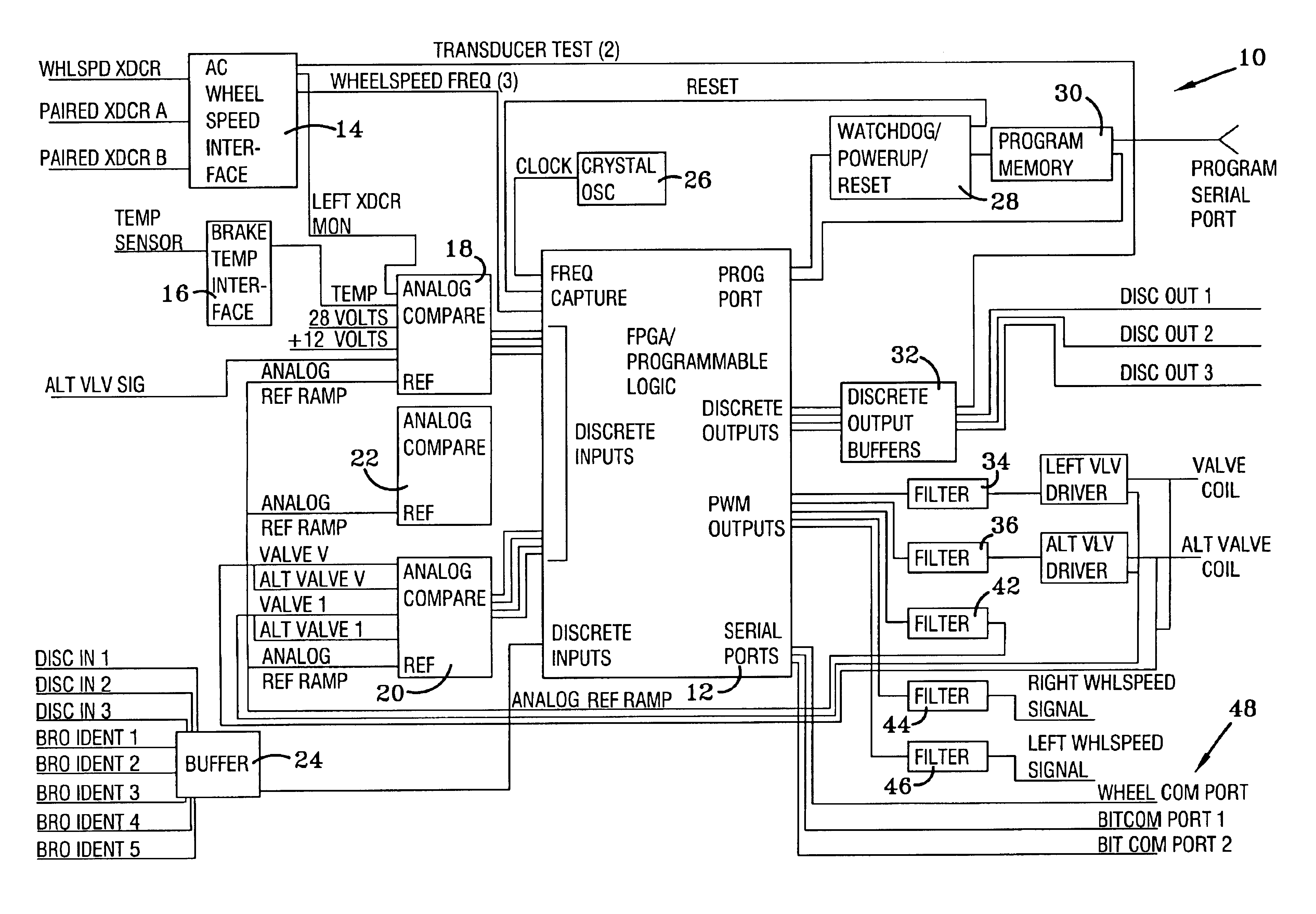
Referring now to the drawings and more particularly to FIG. 1, it can be seen that a brake control system made in accordance with the invention is designated generally by the numeral 10. Again, while the concept of the invention is described in the context of an aircraft brake control system, it will be appreciated that the general concept is applicable to a broad range of control structures.

At the heart of the brake control system 10 is a field programmable gate array (FPGA) 12, which is of sufficient size to accommodate the functions to be performed by the brake control system 10. A wheel speed interface 14 is interconnected between wheel speed transducers and the FPGA 12 to provide wheel speed signals of a frequency corresponding to instantaneous wheel speeds in a manner well known and understood by those skilled in the art. Similarly, a brake temperature interface 16 may be interconnected to an appropriate temperature sensor such as thermocouple, thermistor or the like, to recei...


PUM


Abstract

A brake control system for a wheeled vehicle includes a field programmable gate array configured to perform the algorithm of brake control subsystems in a typical brake control system for a wheeled vehicle. The brake control subsystems typically include anti-skid control, brake temperature monitoring, built-in tests, and, in the case of an aircraft, nose wheel steering. The system also includes wheel speed sensors, brake temperature monitors, brake valves and associated control circuits, and brake valve monitors respecting brake valve current and voltage. The use of field programmable gate arrays to configure a brake control system avoids the obsolescence and shortened life of control systems previously dependent upon microprocessors and the like.

Description

TECHNICAL FIELDThe invention herein resides in the art of electronic control systems and, more particularly, to control systems for aircraft brakes. Specifically, the invention relates to a brake control system defined by field programable gate arrays and application specific integrated circuits such as to provide a hardware implementation of a software based brake control / anti-skid algorithm, including brake-by-wire, automatic braking, and brake temperature monitoring. The invention is generally applicable to a broad range of control systems, of which aircraft brakes are simply an example.BACKGROUND ARTThe invention presented in detail herein is set forth with respect to an aircraft braking system and, more specifically, to the anti-skid control portion of such a braking system. The invention, however, contemplates adaptation to a broad range of controls in which field programmable gate arrays may be employed for purposes which will become apparent herein.In the prior art of contro...

Claims


Application Information

Patent Timeline
IPC IPC(8): B62D6/00B60T8/32B60T8/17B60T8/88B60T17/18B64C25/42
CPCB60T8/1703B64C25/42B60T8/885
Inventor BECK, ARNOLD A.HILL, JAMES L.HURLEY, RALPH J.
Owner AIRCRAFT BRAKING SYST
Why Eureka
Try Eureka