Film Covered Electrical Device, Frame Member, And Housing System For Film Covered Electrical Device

Active Publication Date: 2008-07-17
NEC CORP +1
View PDF6 Cites 41 Cited by
  • Summary
  • Abstract
  • Description
  • Claims
  • Application Information

AI Technical Summary

Benefits of technology

[0030]Also, the container for the film covered electric device according to the present invention may have a lid having a pressing portion that presses the frame member of the assembled battery housed in the container toward the bottom of the container in which the assembled battery is mounted. Also, in the container for the film covered electric device according to the present Invention, a plurality of projections made of resin and formed on a side wall of the container are each inserted into a plurality of holes, each of which corresponds to each of the projections, and each projection that projects from each

Problems solved by technology

However, the technique for applying pressure to the electric generating element by the holding member which has a plurality of projections had a problem in which the life of the power generation element will differ in the part where pressure is applied by the holding member, and in the part where no pressure is applied.
In order to suppress the non-uniform application of pressure, even if it applies uniform pressure to the entire surface of the electric generating e

Method used


Image

  • Film Covered Electrical Device, Frame Member, And Housing System For Film Covered Electrical Device
  • Film Covered Electrical Device, Frame Member, And Housing System For Film Covered Electrical Device
  • Film Covered Electrical Device, Frame Member, And Housing System For Film Covered Electrical Device

Examples


Example

First Embodiment

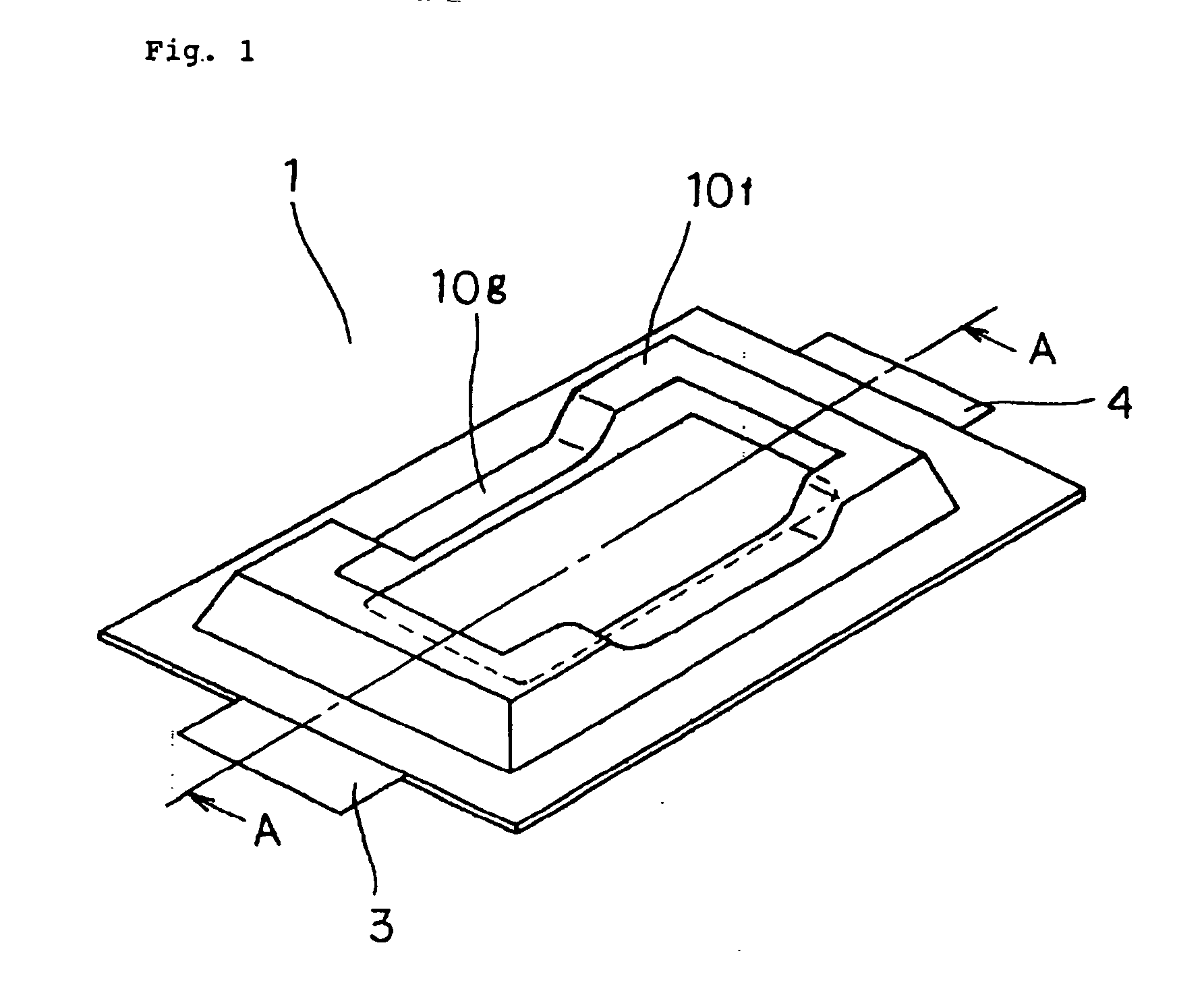
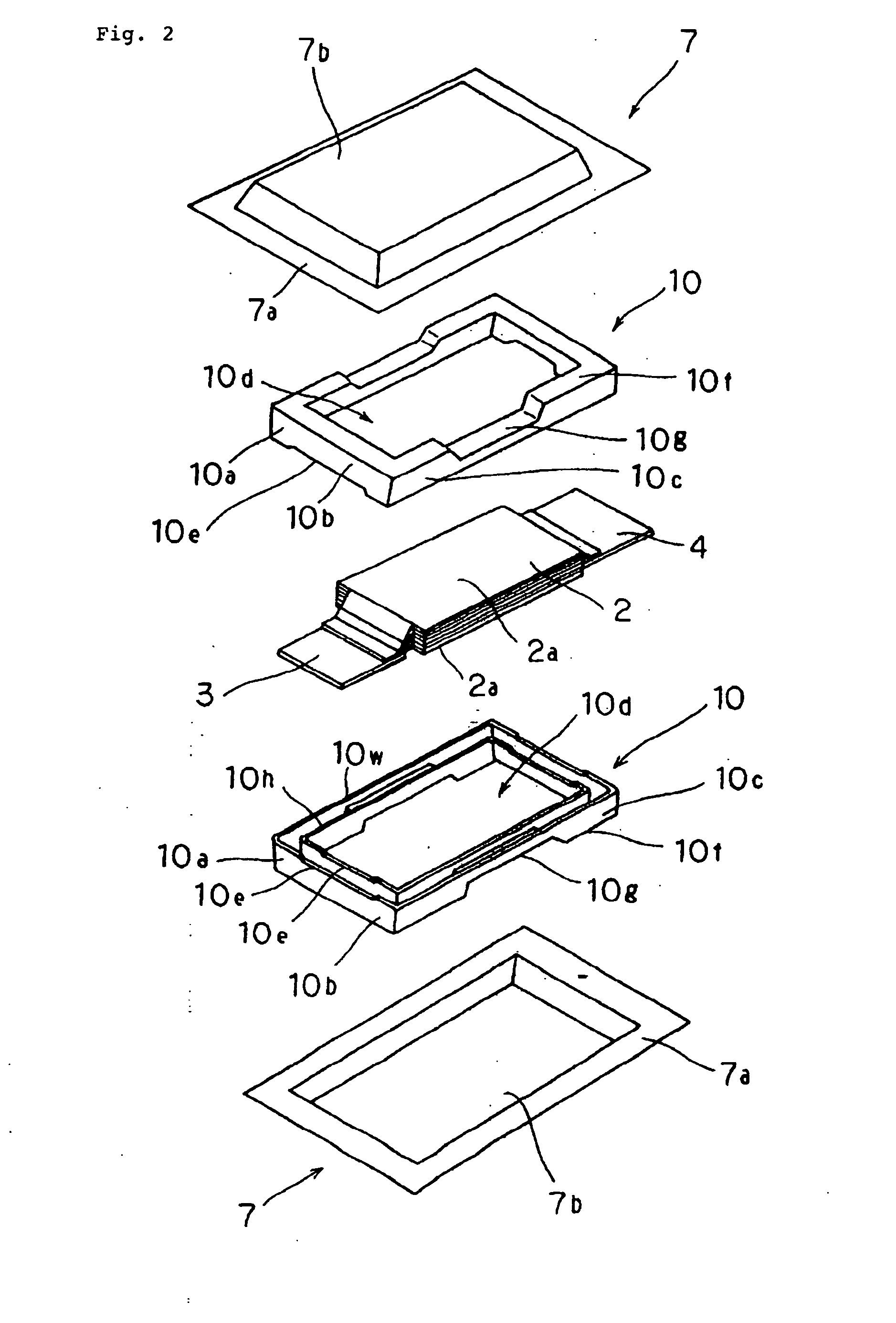
[0042]FIG. 1 is a perspective external view schematically showing a laminated battery of a first embodiment, and FIG. 2 is a perspective exploded view schematically showing the laminated battery according to the first embodiment.

[0043]FIG. 3a is a cross-sectional view taken along line A-A in FIG. 1, and

[0044]FIG. 3b is a plane perspective view of the laminated battery.

[0045]Laminated battery 1 has a structure in which electric generating element 2 having a cathode-side active electrode, an anode-side active electrode, and an electrolytic solution, and frame member 10 that is arranged to surround the periphery of electric power generating element 2 and has first portion 10f with a thickness larger than that of electric power generating element 2, are sealed by four sides of heat-sealed portion 7a of laminate film 7 formed by laminating a metal film, like aluminum, and a heat-sealed resin film.

[0046]Electric power generating element 2 in laminated battery 1 may be a la...

Example

Second Embodiment

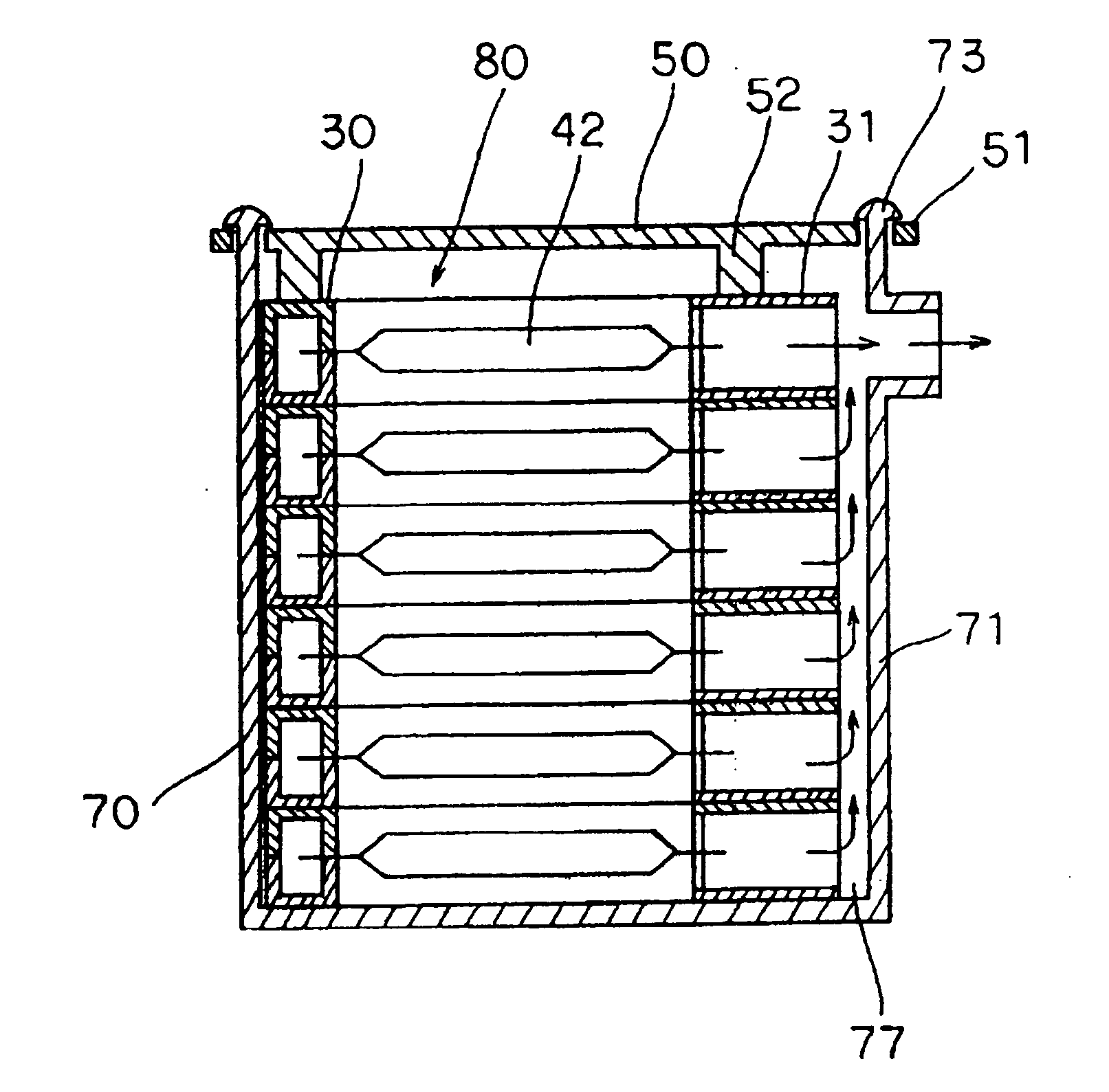
[0068]FIG. 6 is a perspective exploded view schematically showing a laminated battery of a second embodiment.

[0069]In the first embodiment, frame member 10 that holds electric power generating element 2 is sealed in laminate film 7 together with electric power generating element 2, whereas frame member 30 of the second embodiment is arranged outside laminate film 47.

[0070]Frame member 30 of the second embodiment has as its object preventing the local application of strong pressure to main surface 42a of electric power generating element 42 without causing an increase in weight, when the battery is held, similarly to frame member 10 of the first embodiment.

[0071]Therefore, the arrangement thereof is similar to that of frame member 10. Specifically, frame member 30 is arranged so as to surround the periphery of power electric generating element 42 and has first portion 30f with a thickness larger than that of electric power generating element 42. Frame member 30 can b...


PUM


Abstract

Disclosed is a laminate cell (1) comprising an electric power generating element (2) and a laminate film (7) so arranged as to surround the electric power generating element (2). The laminate cell (1) further comprises a frame member (10) which surrounds and holds the electric power generating element (2) and has a first portion (10f) with a thickness larger than that of the electric power generating element (2).

Description

TECHNICAL FIELD[0001]The present invention relates to a film covered electric device, a frame member, and a housing system for a film covered electric device.BACKGROUND ART[0002]In recent years, an electric automobile or a hybrid electric automobile (hereinafter, simply called “electric automobile”) mounted with a battery for driving a motor has been rapidly developed. The battery mounted on the electric automobile is required as a matter of course to have reduced weight in order to improve drivability and mileage per charge. In order to reduce battery weight, a film covered battery has been developed using a laminate material formed Into a thin film by laminating a metal layer, like aluminum, and a thermal-melt resin layer through an adhesive layer on the covering body. The laminate material generally has a structure, in which both surfaces of the thin metal layer, like aluminum, are covered with thin resin layers, and is resistant to acid and alkali and is lightweight and flexible...

Claims


Application Information

Patent Timeline
IPC IPC(8): H01M2/12H05K7/20H01M2/02H01G9/08H01M50/119H01M50/121H01M50/124H01M50/227H01M50/367
CPCH01G9/016Y02T10/7022H01G9/155H01G11/10H01G11/12H01G11/76H01G11/80H01G11/82H01M2/021H01M2/0275H01M2/1072H01M2/1235H01M2/1252H01M10/0486H01M10/4207H01M10/5004H01M10/5032H01M10/5067Y02E60/13H01G9/08H01M10/6563H01M10/647H01M10/613Y02T10/70Y02E60/10H01M50/342Y02P70/50H01M50/367H01M50/121H01M50/124H01M50/227H01M50/119H01G11/18H01G11/74H01M2220/20
Inventor KANAI, TAKESHINAKANO, HISAKO
Owner NEC CORP
Why Eureka
Try Eureka