
Flying entertainment vehicle

a technology for entertainment vehicles and flying aircraft, which is applied in the field of flying entertainment vehicles (or powered parawing aircraft), can solve the problems of preventing observers from truly believing the character, scarce real estate or space in many entertainment venues such as theme parks, and severely restricting the range and direction of travel of characters, so as to achieve enhanced entertainment experience and hinder flight

Active Publication Date: 2010-11-11
DISNEY ENTERPRISES INC
View PDF7 Cites 7 Cited by
  • Summary
  • Abstract
  • Description
  • Claims
  • Application Information

AI Technical Summary

Benefits of technology

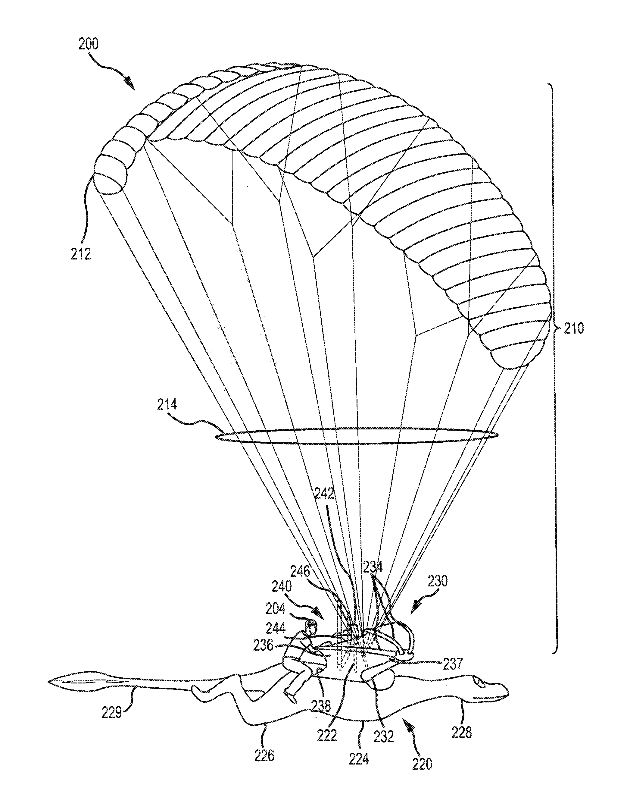
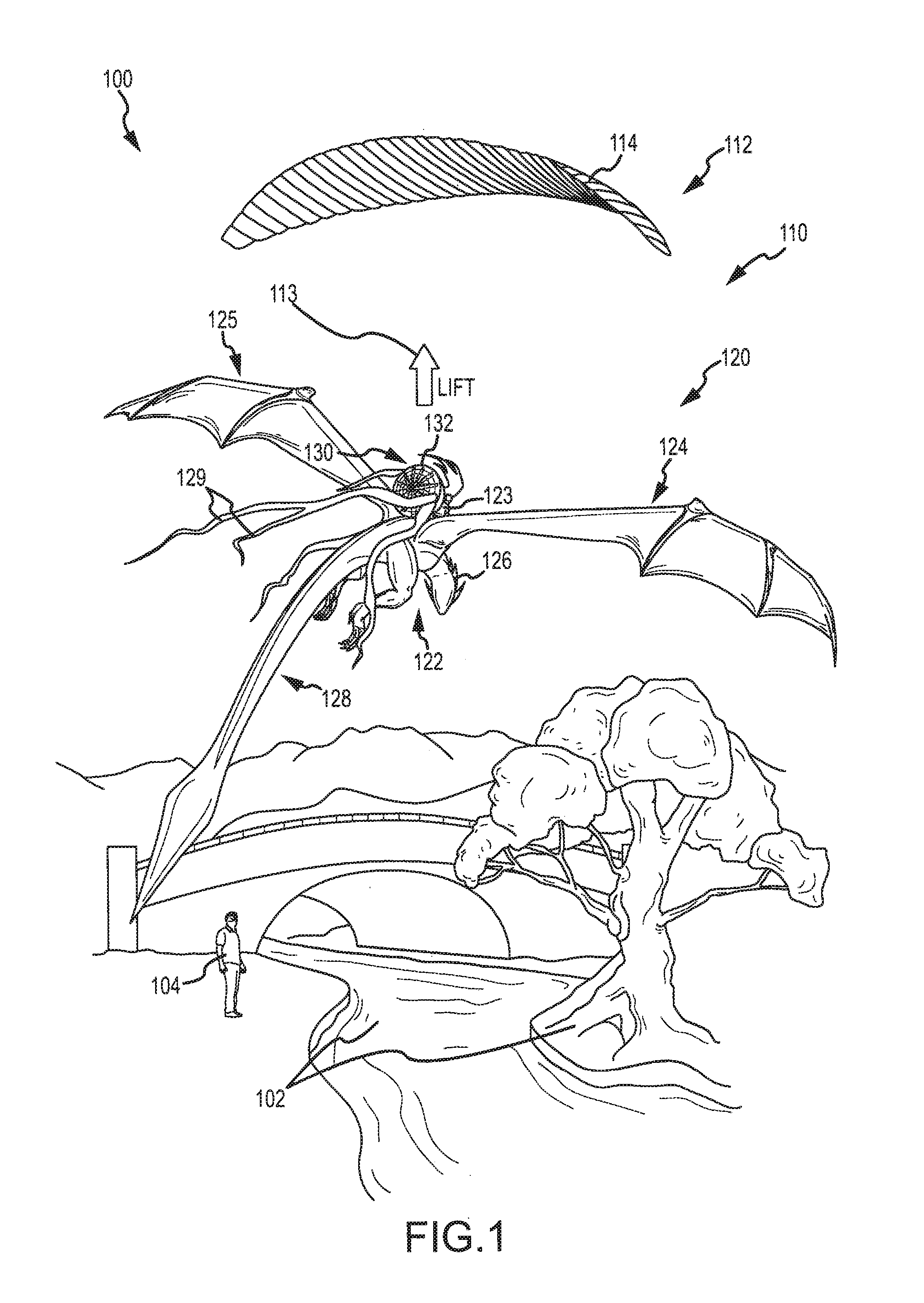
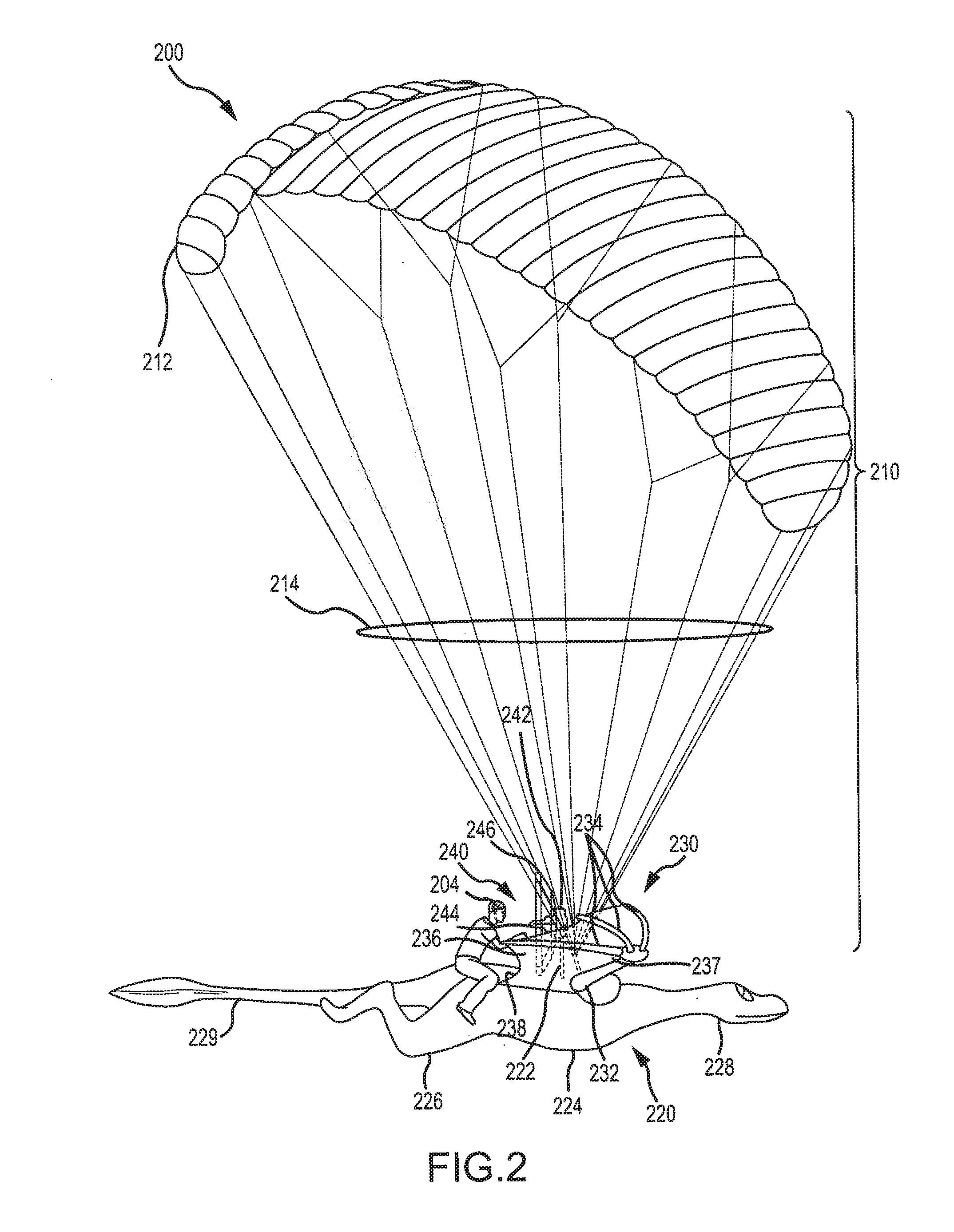
[0009]It was realized that are many situations where an entertainment experience could be enhanced by providing a flying entertainment vehicle or platform in which the method of lift and / or thrust (aerodynamic lift system that causes the vehicle to fly) were disguised or hidden. Further, it was realized that it may be useful to provide show or entertainment elements on such a vehicle or platform that were not provided for aerodynamic functionality (and, in some cases, hinder flight by adding drag) but, instead, to provide a visually interesting effect such as to provide an animatronic character or the like. For example, many theme parks would benefit from having characters that have the ability to fly (e.g., an animated or other movie with a flying dragon, a fairy, a super hero, and so on) be displayed as flying or to provide part of a storytelling experience by flying.

Problems solved by technology

In the past, flying characters were typically suspended in the air using motor-controlled cables or a boom, which severely limited the character's range and direction of travel and prevented observers from truly believing the character could fly (little or no suspension of disbelief).
Additionally, real estate or space in many entertainment venues such as theme parks is scarce and expensive, causing the inventors to look toward the sky for providing entertainment.

Method used


Image

  • Flying entertainment vehicle
  • Flying entertainment vehicle
  • Flying entertainment vehicle

Examples


Embodiment Construction

[0031]The present invention is generally directed toward a flying entertainment vehicle or platform that may be used in an entertainment facility or venue (such as at a theme or amusement park). The following description begins with a general overview of aspects of such a flying entertainment vehicle and then proceeds to more specific descriptions of features of that may be provided with particular exemplary embodiments or implementations with reference to the attached figures.

[0032]The flying entertainment vehicle may be used to display a dragon or other creature as it flies over heads of observers. To this end, the flying entertainment vehicle may include a vehicle frame providing a cockpit for a pilot and providing a set of controls. The vehicle frame may also include a thrust assembly (e.g., a motor-driven propeller) to propel the vehicle at a takeoff and flying speed. The vehicle frame may then be disguised with a set of show elements such as a character body provided about the...


PUM


Abstract

An apparatus for use as a flying entertainment vehicle. The apparatus includes a lift system, such as a parawing, that is inflated by air to generate lift and further includes a vehicle frame attached to the lift system such as by suspension lines that also space the lift system apart from the vehicle frame. The apparatus includes a thrust assembly supported on the vehicle frame that is operable to propel the vehicle at a flight speed at which the lift system is operated, e.g., the parawing is inflated, to generate lift to suspend the vehicle frame above the ground. The apparatus includes show elements that may be supported on or by the vehicle frame and be configured to be lift neutral. The show elements function to distract observers away from the lift system such as by appearing to provide the lift or features that cause the vehicle frame to fly.

Description

CROSS-REFERENCE TO RELATED APPLICATIONS[0001]This application claims the benefit of U.S. Provisional Application No. 61 / 176,484 filed May 7, 2009, which is incorporated herein by reference in its entirety.BACKGROUND OF THE INVENTION[0002]1. Field of the Invention[0003]The present invention relates, in general, to aircraft including ultralight aircraft, and, more particularly, to a flying entertainment vehicle (or powered parawing aircraft) including a lift system such as a parawing, a vehicle frame suspended below and lifted in flight by the lift system, and one or more show elements mounted on the vehicle frame that are configured to appear to an observer to provide or affect flight of the flying entertainment vehicle while being designed to be substantially lift neutral (e.g., providing more drag than lift for the frame) in function.[0004]2. Relevant Background.[0005]Mobile entertainment platforms are either stationary when operating or operate on slow moving ground vehicles such ...

Claims


Application Information

Patent Timeline
Patent Type & Authority Applications(United States)
IPC IPC(8): B64C39/02B64C31/00B64C3/00B64C5/02B64C31/036
CPCB64C31/036
Inventor DOHI, ANTHONY PAULWATSON, SCOTT FRAZIERTROWBRIDGE, ROBERT SCOTT
Owner DISNEY ENTERPRISES INC
Learn More