Dynamic compensation of chromatic point sensor intensity profile data selection

a chromatic point sensor and intensity profile technology, applied in the field of precision measurement instruments, can solve problems such as undesirable measurement variations in known implementations

Active Publication Date: 2010-11-11
MITUTOYO CORP
View PDF17 Cites 28 Cited by
  • Summary
  • Abstract
  • Description
  • Claims
  • Application Information

AI Technical Summary

Benefits of technology

The invention provides an improved method for measuring distances by using multiple sets of specific data limits based on different indices. These data limits are adjusted automatically to account for changes in signal strength or detectors over time during use. This ensures accurate measurements even when there are significant differences between the initial calibration conditions and those encountered later during usage.

Problems solved by technology

This patent describes how optical height sensors can measure surfaces using chromatic confocal techniques. The problem being addressed is reducing measuring errors caused by various factors when trying to accurately determine the position of a surface based on the detected light levels at different wavelanges.

Method used


Image

  • Dynamic compensation of chromatic point sensor intensity profile data selection
  • Dynamic compensation of chromatic point sensor intensity profile data selection
  • Dynamic compensation of chromatic point sensor intensity profile data selection

Examples


Embodiment Construction

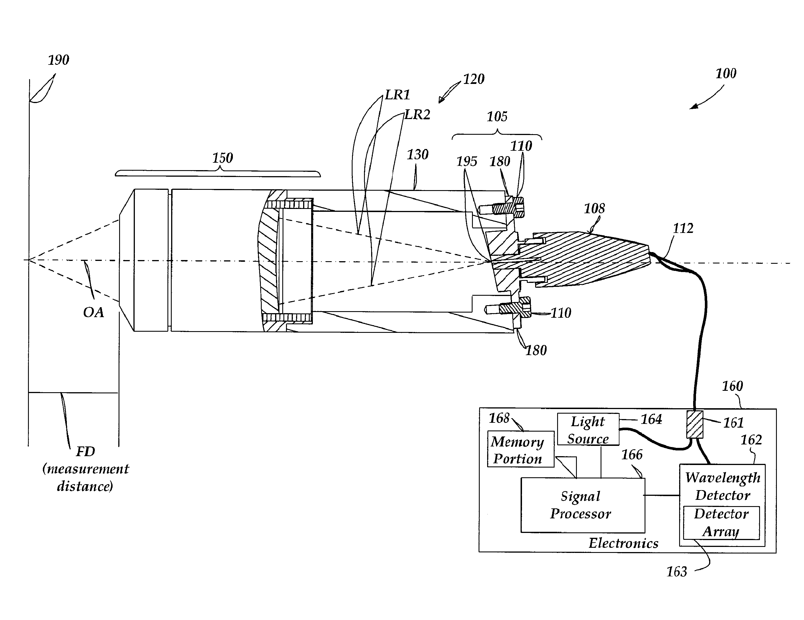
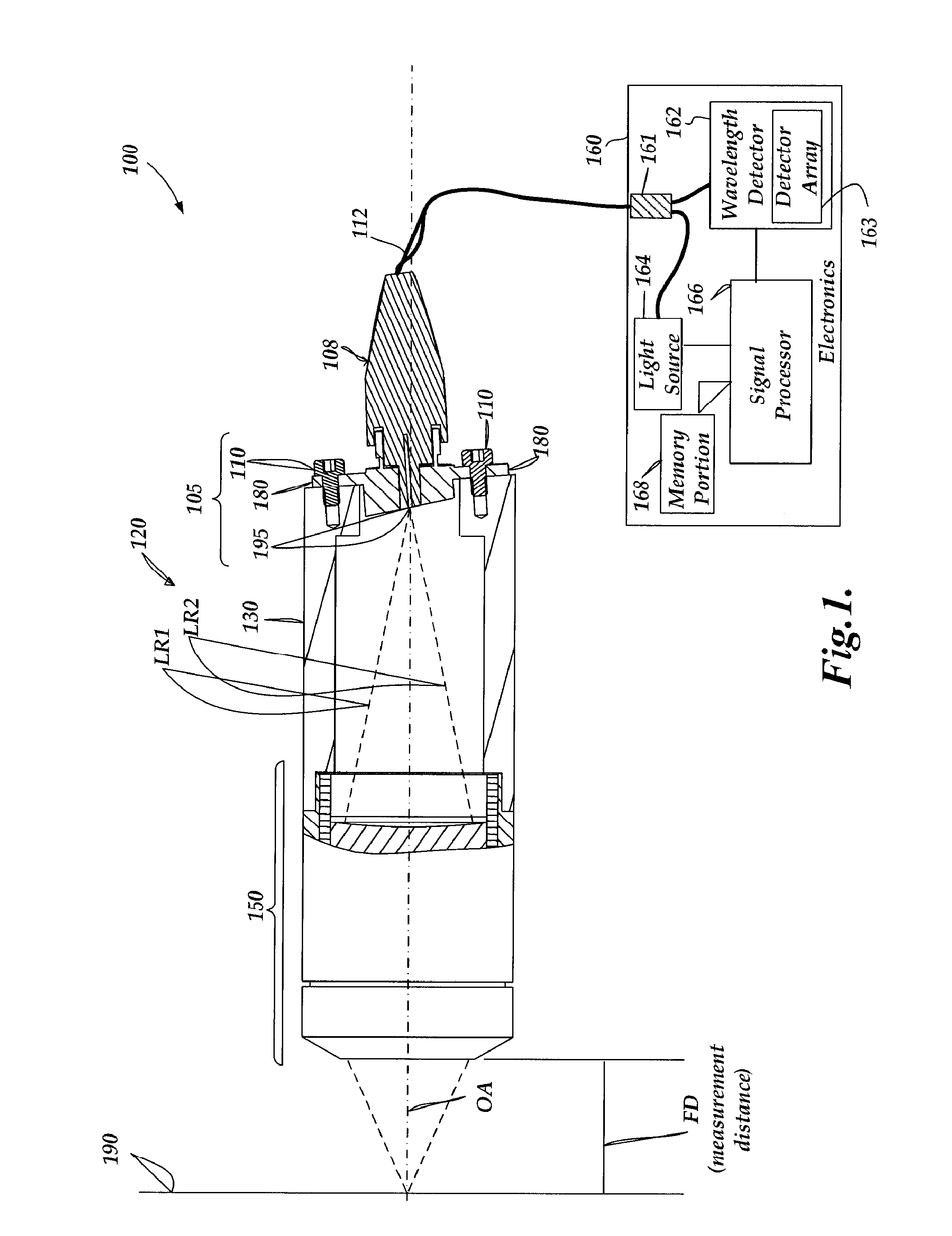
[0036]FIG. 1 is a block diagram of an exemplary chromatic point sensor 100. As shown in FIG. 1, the chromatic point sensor 100 includes an optical pen 120 and an electronics portion 160. The optical pen 120 includes an in / out fiber optic sub-assembly 105, a housing 130, and an optics portion 150. The in / out fiber optic sub-assembly 105 includes a mounting element 180, that may be attached to the end of the housing 130 using mounting screws 110. The in / out fiber optic sub-assembly 105 receives an in / out optical fiber (not shown) through a fiber optic cable 112 which encases it, and through a fiber optic connector 108. The in / out optical fiber outputs an output beam through an aperture 195, and receives reflected measurement signal light through the aperture 195.

[0037]In operation, light emitted from the fiber end through the aperture 195 is focused by the optics portion 150, which includes a lens that provides an axial chromatic dispersion such that the focal point along the optical ...


PUM


Abstract

In a chromatic point sensor, distance measurements are based on a distance-indicating subset of intensity profile data, which is selected in a manner that varies with a determined peak position index coordinate (PPIC) of the profile data. The PPIC indexes the position a profile data peak. For profile data having a particular PPIC, the distance-indicating subset of the profile data is selected based on particular index-specific data-limiting parameters that are indexed with that same particular PPIC. In various embodiments, each set of index-specific data-limiting parameters indexed with a particular PPIC characterizes a distance-indicating subset of data that was used during distance calibration operations corresponding to profile data having that PPIC. Distance-indicating subsets of data may be compensated to be similar to a corresponding distance-indicating subset of data that was used during calibration operations, regardless of overall intensity variations and detector bias signal level variations.

Description


Claims


Application Information

Patent Timeline
Owner MITUTOYO CORP
Why Eureka
Try Eureka