
Coordinate input apparatus

A coordinate input device and coordinate technology, applied in the input/output process of data processing, instruments, electrical digital data processing and other directions, can solve the problem of not being able to input easily at any time.

Inactive Publication Date: 2008-06-18
WACOM CO LTD
View PDF2 Cites 17 Cited by
  • Summary
  • Abstract
  • Description
  • Claims
  • Application Information

AI Technical Summary

Problems solved by technology

However, when using this electromagnetic induction method for input, a special position indicator is required, so that input cannot be easily performed at any time

Method used


Image

  • Coordinate input apparatus
  • Coordinate input apparatus
  • Coordinate input apparatus

Examples


Embodiment Construction

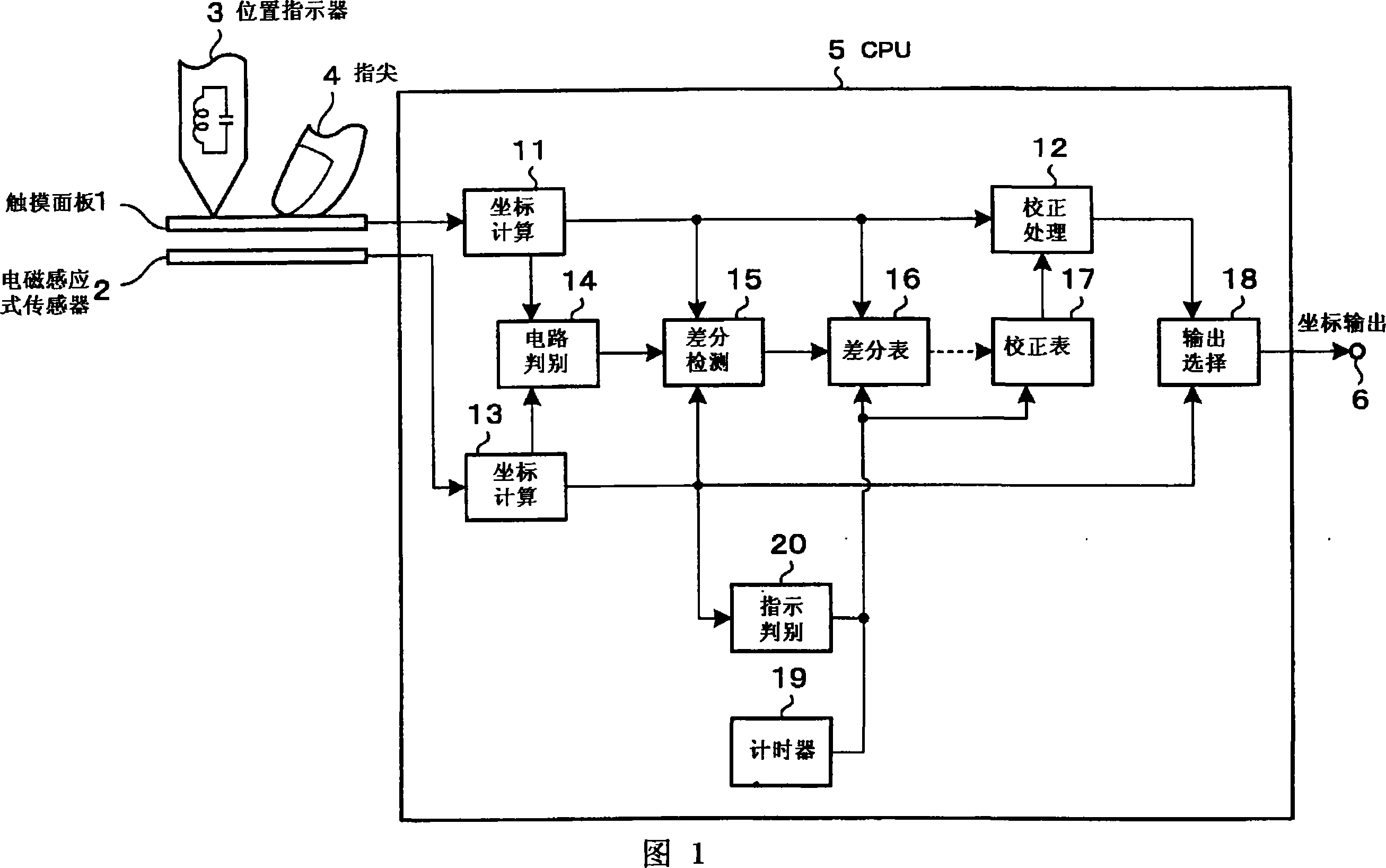
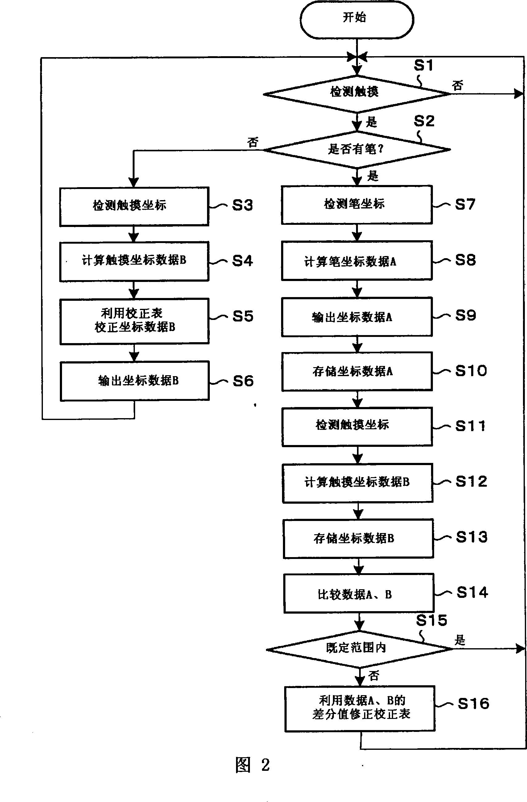
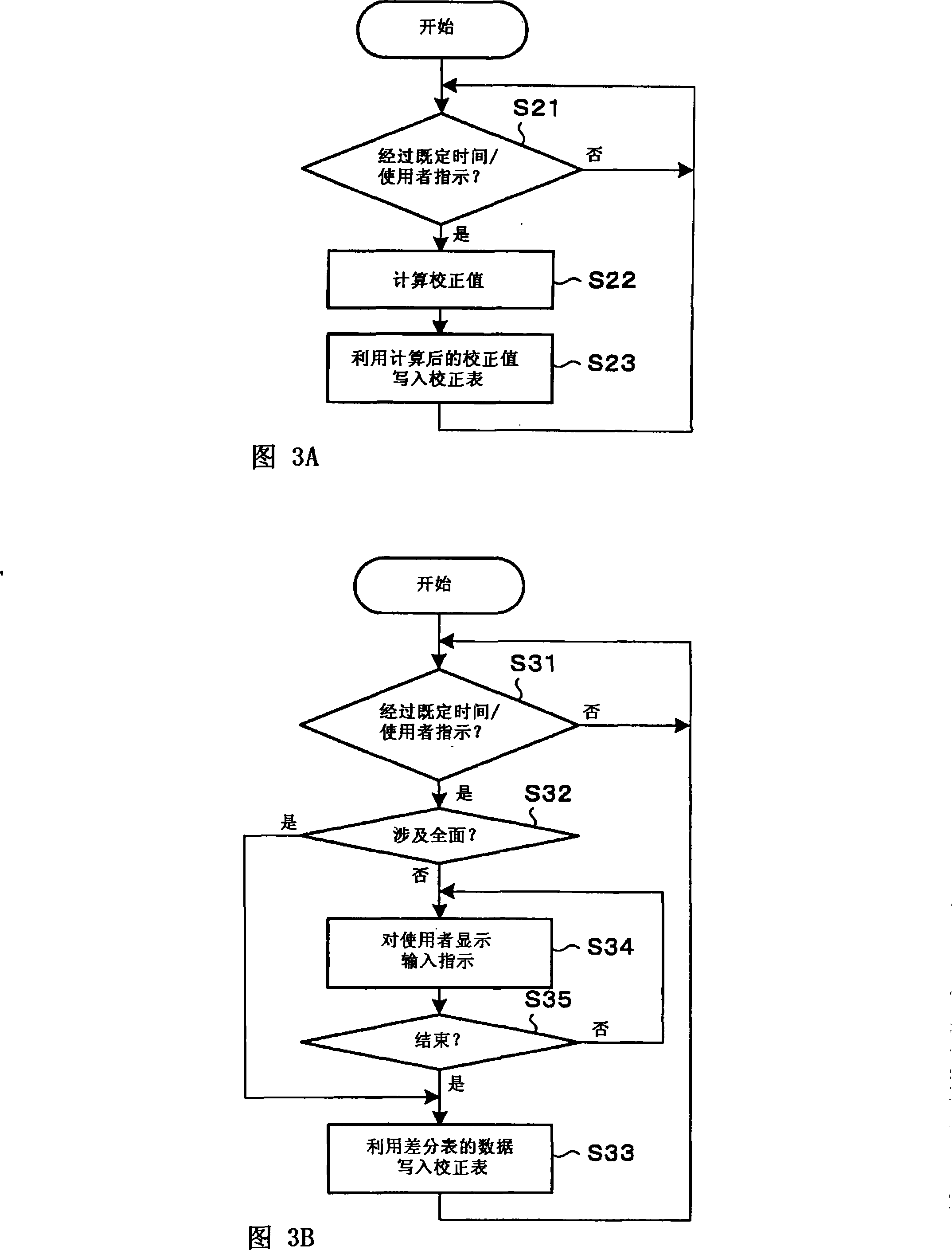
[0050] A coordinate input device using the present invention will be described with reference to FIGS. 1 to 3 . First, FIG. 1 shows a block diagram of an embodiment of the coordinate input device of the present invention.

[0051] In FIG. 1 , a touch panel (pressure sensitive sensor) 1 and an electromagnetic induction sensor 2 are stacked in a coordinate input device using the present invention. A touch panel (pressure sensitive sensor) 1 is described in Patent Document 1, for example, as a first input device that needs to be corrected when an input value is taken out. The electromagnetic induction sensor 2 is, for example, described in Patent Document 2 as a second input device that does not require correction when taking out an input value. The touch panel 1 must be exposed on the input surface, the electromagnetic induction sensor 2 can be installed separately, and a liquid crystal display panel or the like can be arranged between the touch panel 1 and the electromagnetic ...


PUM


Abstract

The present invention provides a coordinate input device, easily correcting one input value needed being corrected of a first input value and a second input value. CPU input value for coordinate calculation supplied from a touching panel is supplied to a correction processing assembly to correct to be a correct value after utilizing conversion calculating assembly to the coordinate. In another aspect, the input value of CUP supplied from the electromagnetic sensor is supplied to the coordinate calculating assmebly and changed to a high precise coordinate. The input signal representing calculating assembly from the coordinate is supplied to the identical juding assembly, the juding signal is supplied to the differential detection assembly, detecting the difference of the coordinate changed by differnt input values respectively. The differential value is stored in the correction list by ddifferential list, the differential value is added and subtracted with the coordinate value calculated by the coordinate calculating assembly of the correction processing assembly. The coordinate value is catched from the coordinate output by output selecting assembly to select the coordinate value.

Description

technical field [0001] The present invention relates to a coordinate input device suitable for use in a digitizer in connection with, for example, a computer. Background technique [0002] For example, in a touch panel (pressure sensor), in order to cope with long-term changes in the resistive film, it is necessary to correct the input value before taking it out (see Patent Document 1). [0003] As shown in Fig. 4, a four-wire type touch panel is composed of two surfaces formed of arbitrary resistive films, on one surface, electrodes are provided at both ends in the X-axis direction, and on the other surface, electrodes are provided on both ends in the Y-axis direction. Electrodes are provided at both ends. When the surface of the touch panel is pressed, the position is detected by bringing the resistive films on both sides of the pressed point (position) into contact. [0004] That is, through the contact of the resistive film on both sides, during one period of contact, ...

Claims


Application Information

Patent Timeline
Patent Type & Authority Applications(China)
IPC IPC(8): G06F3/041G06F3/045G06F3/046
CPCG06F3/0418G06F3/045G06F3/0416G06F3/046G06F3/04186
Inventor 小野田直人山本定雄
Owner WACOM CO LTD
Learn More