Image coding apparatus, image decoding apparatus, image coding method, and image decoding method

a coding apparatus and image technology, applied in the field of image coding apparatus, image coding apparatus, image coding method, can solve the problems of discontinuous boundary, inability to re-constitution, and inability to achieve satisfactory rendition of residual signal, etc., to achieve the effect of improving the efficiency of low bit rate coding that employs interframe mc, suppressing discontinuous waveforms, and improving coding efficiency

Inactive Publication Date: 2010-11-11
NTT DOCOMO INC
View PDF21 Cites 27 Cited by
  • Summary
  • Abstract
  • Description
  • Claims
  • Application Information

AI Technical Summary

Benefits of technology

[0024]The present invention was conceived in view of these problems, an object thereof being to provide an image coding apparatus, image decoding apparatus, image coding method, and image decoding method that make it possible to use relatively simple computation to perform processing, with respect to a prediction frame image generated by block-based motion-compensated interframe prediction (MC), to adaptively smooth a discontinuous waveform generated between MC blocks of the prediction frame image, whereby the efficiency of low bit rate coding that employs interframe MC can be improved.
[0029]According to this constitution, smoothing is performed for pixels located at the boundaries of adjoining partial image regions on the basis of predetermined evaluation criteria, with respect to the prediction image, and it is therefore possible to perform correction in the direction in which only the smoothing processing, that corrects discontinuity in partial image regions, is allowed. It is therefore possible to improve the coding efficiency by suppressing discontinuous waveforms generated in the prediction residual. Accordingly, it is possible to use relatively straightforward computation to perform processing, with respect to a prediction frame image generated by block-unit motion-compensated interframe prediction (MC), to adaptively smooth a discontinuous waveform generated between MC blocks of the prediction frame image, whereby the efficiency of low bit rate coding that employs interframe MC can be improved.

Problems solved by technology

However, when coding is carried out with a high compression ratio, a satisfactory rendition of the residual signal is not possible and the discontinuous boundaries are sometimes apparent and perceived as distortion.
Further, it has been identified that, because the DCT is also a closed orthogonal transform in fixed blocks, in cases where the transform basis coefficients are reduced as a result of coarse quantization, the signal waveform which naturally connects between blocks cannot be reconstituted and unnatural distortion is generated between blocks (block distortion).

Method used


Image

  • Image coding apparatus, image decoding apparatus, image coding method, and image decoding method
  • Image coding apparatus, image decoding apparatus, image coding method, and image decoding method
  • Image coding apparatus, image decoding apparatus, image coding method, and image decoding method

Examples


first embodiment

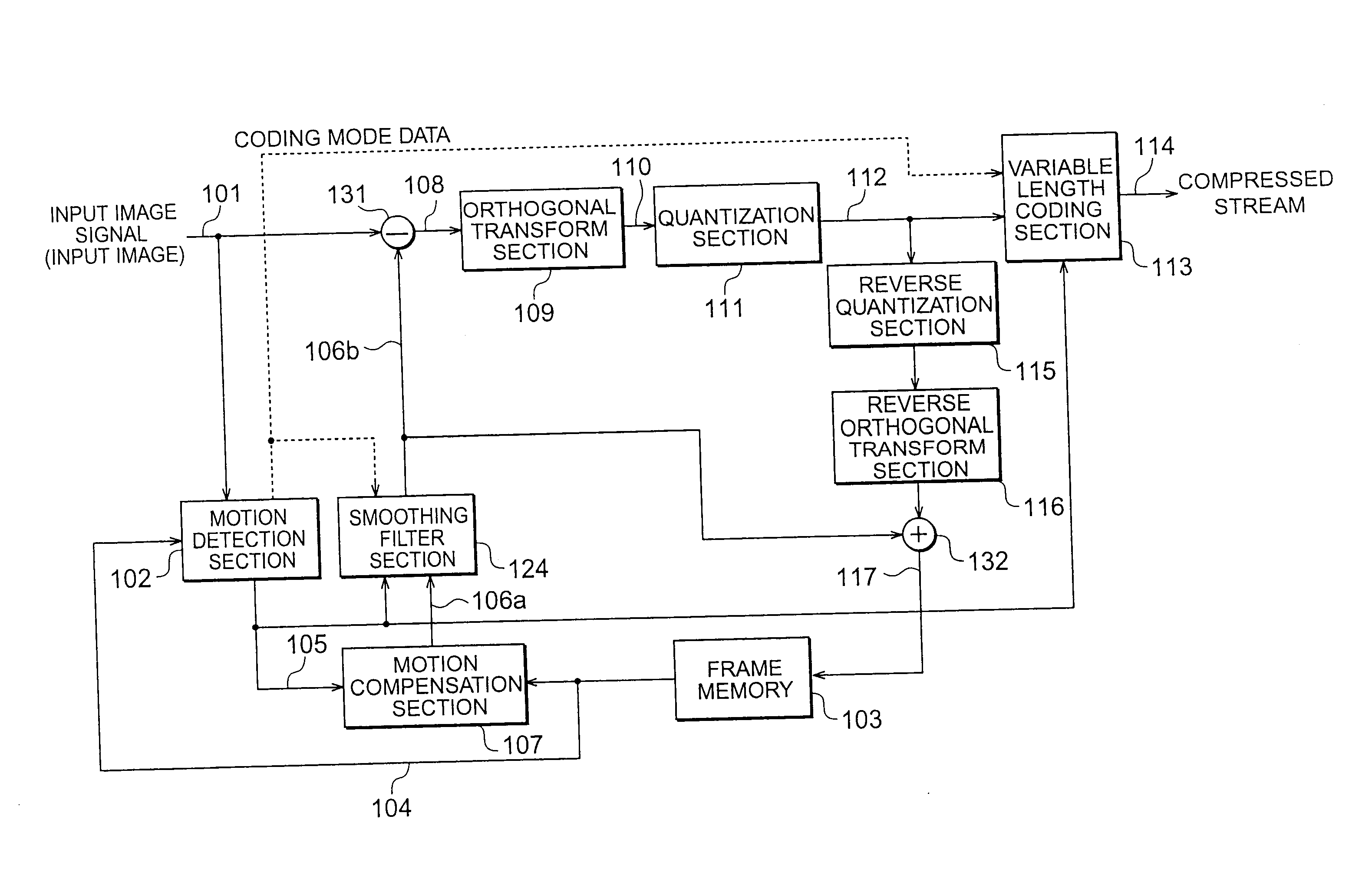
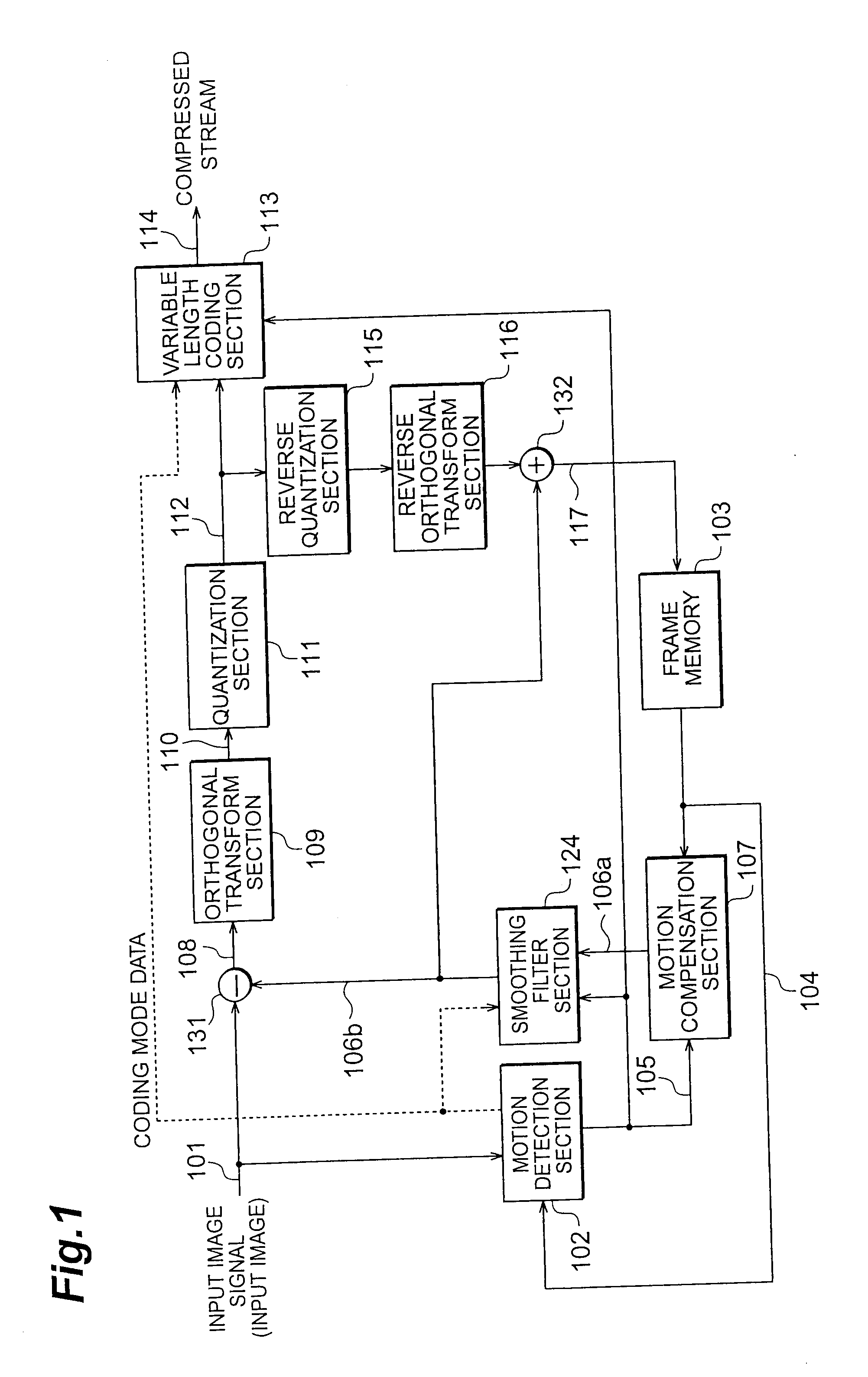
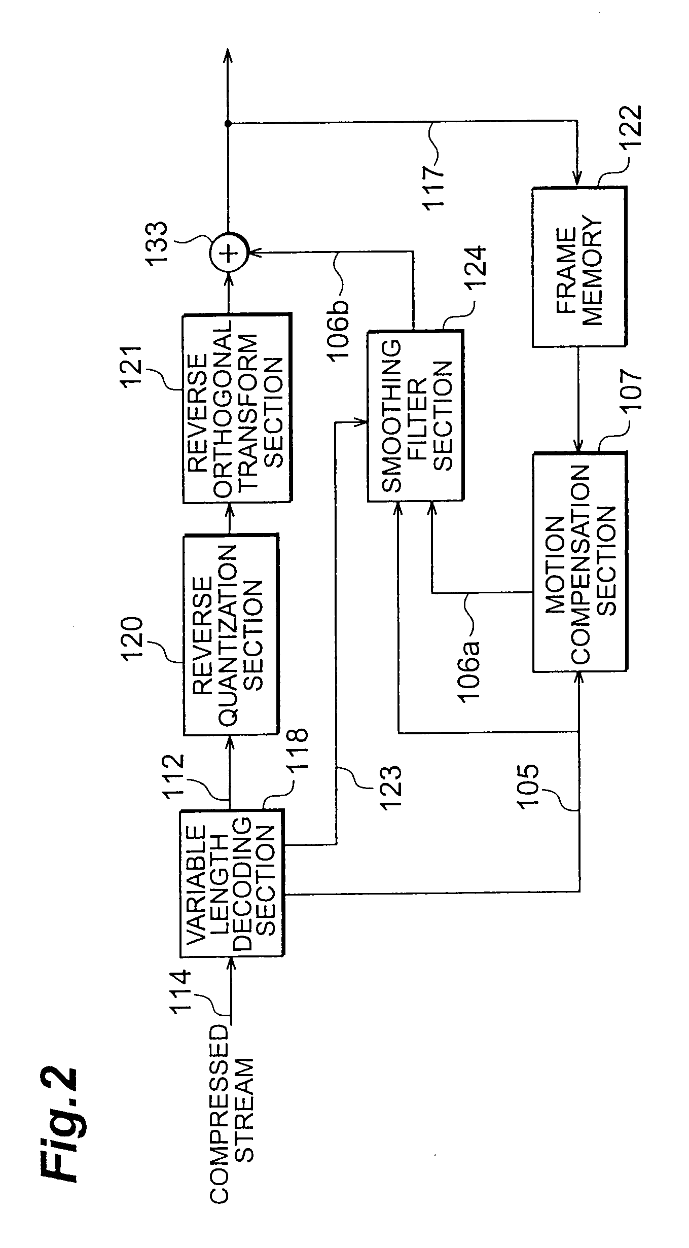
[0057]FIG. 1 is a block diagram showing the constitution of the image coding apparatus according to the first embodiment of the present invention, and FIG. 2 is a block diagram showing the constitution of the image decoding apparatus. The image coding apparatus shown in FIG. 1 performs efficient image coding on account of being constituted to reduce redundancy in a temporal direction by means of MC, quantify spatial discontinuity between individual MC blocks with respect to the prediction image obtained by means of the MC, and adaptively perform smoothing filter processing in accordance with the conditions.

[0058]The MC procedure of this image coding apparatus is substantially the same as the method described in the conventional example. An outline of this procedure is provided in FIG. 21 and an outline of the block matching processing employed in the motion vector detection is as shown in FIGS. 22A to 22D. However, the MC blocks can be defined by uniformly divided units into which m...

second embodiment

[0113]FIG. 12 is a block diagram showing the constitution of the image coding apparatus according to the second embodiment of the present invention, and FIG. 13 is a block diagram showing the constitution of the image decoding apparatus thereof. The second embodiment relates to an apparatus constituted by introducing the smoothing filter of the present invention described above to an image coding and decoding apparatus according to a compression coding system that applies the technique known as Matching Pursuits. Image coding systems that use Matching Pursuits include that disclosed by R. Neff et al, “Very Low Bit-rate Video Coding Based on Matching Pursuits”, IEEE Trans. on CSVT, vol. 7, pp. 158-171, February 1997. With Matching Pursuits, a prediction residual image signal f to be encoded can be rendered as per the following formula by using an over-complete basis set G prepared in advance that comprises n types of basis gkεG (1≦k≦n).

f=(∑i=0m-1〈si,gki〉gki)+rm(1)

[0114]Here, m is the...

third embodiment

[0131]A third embodiment of the present invention will now be described. The third embodiment describes another smoothing filter section. This smoothing filter section is a modification of the smoothing filter sections 124 and 224 described in the above first and second embodiments respectively, and because this filter simply substitutes for the smoothing filter sections 124 and 224, this filter can be applied to the image coding apparatus and image decoding apparatus shown in FIGS. 1 and 2 or FIGS. 12 and 13 respectively. The internal constitution is also the same as that in FIG. 5.

[0132]With the smoothing filter section according to the third embodiment, the block activity level calculation section 125 does not define the block activity level information with respect to the blocks but instead defines this information with respect to the block boundaries. Consequently, the filter can be controlled by uniquely allocating an activity level without the selection of an activity level u...


PUM


Abstract

An input image signal is divided into MC block units and, when coding processing is performed in these divided units, a motion compensation section generates a motion-compensated prediction image by detecting movement amounts in predetermined MC block units, a smoothing filter section performs, with respect to the prediction image, smoothing of pixels located at the boundaries of adjoining MC blocks on the basis of predetermined evaluation criteria, and a prediction residual signal, which is obtained from the difference between the prediction image obtained by the smoothing, and the input image signal, is encoded.

Description

CROSS-REFERENCE TO RELATED APPLICATIONS[0001]This application is a continuation of U.S. application Ser. No. 10 / 480,642, filed Dec. 24, 2003, the entire contents of which is incorporated by reference. U.S. application Ser. No. 10 / 480,642 is a national phase application of PCT / JP02 / 00614 under 35 U.S.C §371, filed Jun. 28, 2002, which claims priority to the Japanese Patent Application JP 2001-199685, filed on Jun. 29, 2001.TECHNICAL FIELD[0002]The present invention relates to an image coding apparatus, an image decoding apparatus, an image coding method, and an image decoding method that perform the transmission and storage of images with a small encoding data volume and that are applied to a mobile image transmission system or similar.BACKGROUND ART[0003]Conventional image coding systems are constituted to divide image frames into blocks of a fixed size and then perform coding processing in these divided units. Typical examples of conventional image coding systems include the MPEG (...

Claims


Application Information

Patent Timeline
Patent Type & Authority Applications(United States)
IPC IPC(8): H04N7/32H04N19/50G06T9/00H04N19/132H04N19/136H04N19/137H04N19/176H04N19/196H04N19/423H04N19/503H04N19/51H04N19/513H04N19/61H04N19/625H04N19/85H04N19/91H04N19/97
CPCH04N19/139H04N19/577H04N19/176H04N19/46H04N19/61H04N19/117H04N19/14H04N19/137H04N19/80H04N19/82H04N19/527H04N19/86H04N19/97H04N19/583H04N19/159
Inventor SEKIGUCHI, SHUNICHIKATO, SADAATSUKOBAYASHI, MITSURUETOH, MINORU
Owner NTT DOCOMO INC
Why Eureka
Try Eureka