Locking plate fast fastening ceiling fan blades

a technology of fast fastening and ceiling fans, which is applied in the direction of liquid fuel engines, vessel construction, marine propulsion, etc., can solve problems such as difficult installation

Active Publication Date: 2010-11-11
AIR COOL INDAL
View PDF4 Cites 11 Cited by
  • Summary
  • Abstract
  • Description
  • Claims
  • Application Information

AI Technical Summary

Benefits of technology

[0008]A locking plate fast fastening ceiling fan blades according to this invention mainly comprises a clamp plate and a pushing board for connecting several pillars of the ceiling fan blades and thus fastening a blade onto the blade rack. On the clamp plate, the pillar opposite to the blade rack is provided with a first nick. A chute is formed in the center of clamp plate, where the pushing board is contained, so that the pushing board may slip in the chute. Further, the clamp plate in the chute is provided with a first wedge unit. The first wedge unit is a first wedge spring plate. One side of the first wedge spring plate is a fixing terminal and connects to the clamp plate; the other ...

Problems solved by technology

However, the blade of conventional ceiling fan is definitely long as a ru...

Method used


Image

  • Locking plate fast fastening ceiling fan blades
  • Locking plate fast fastening ceiling fan blades
  • Locking plate fast fastening ceiling fan blades

Examples


Embodiment Construction

[0014]Now, the present invention will be described more specifically with reference to the following embodiments. It is to be noted that the following descriptions of preferred embodiments of this invention are presented herein for purpose of illustration and description only; it is not intended to be exhaustive or to be limited to the precise form disclosed.

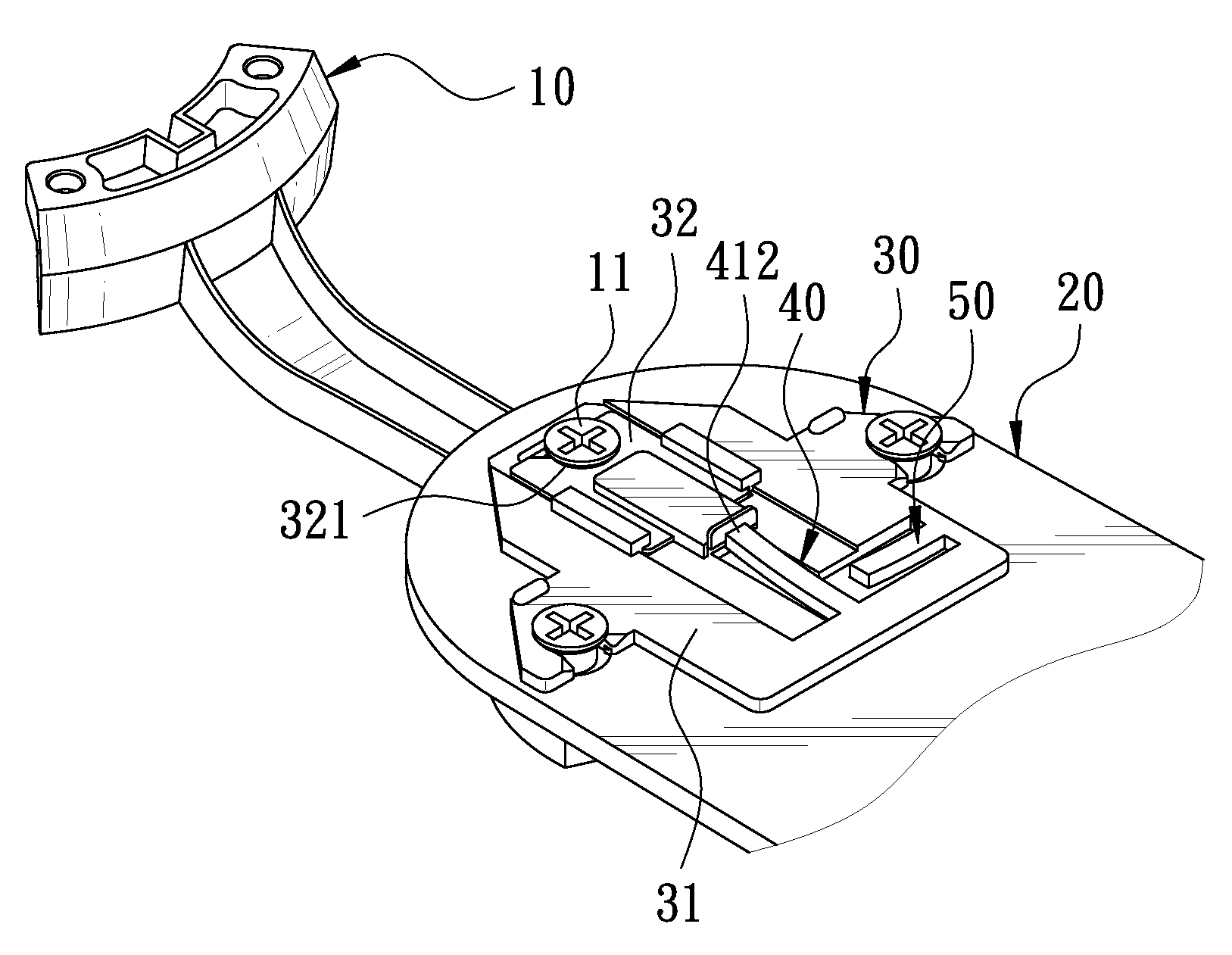
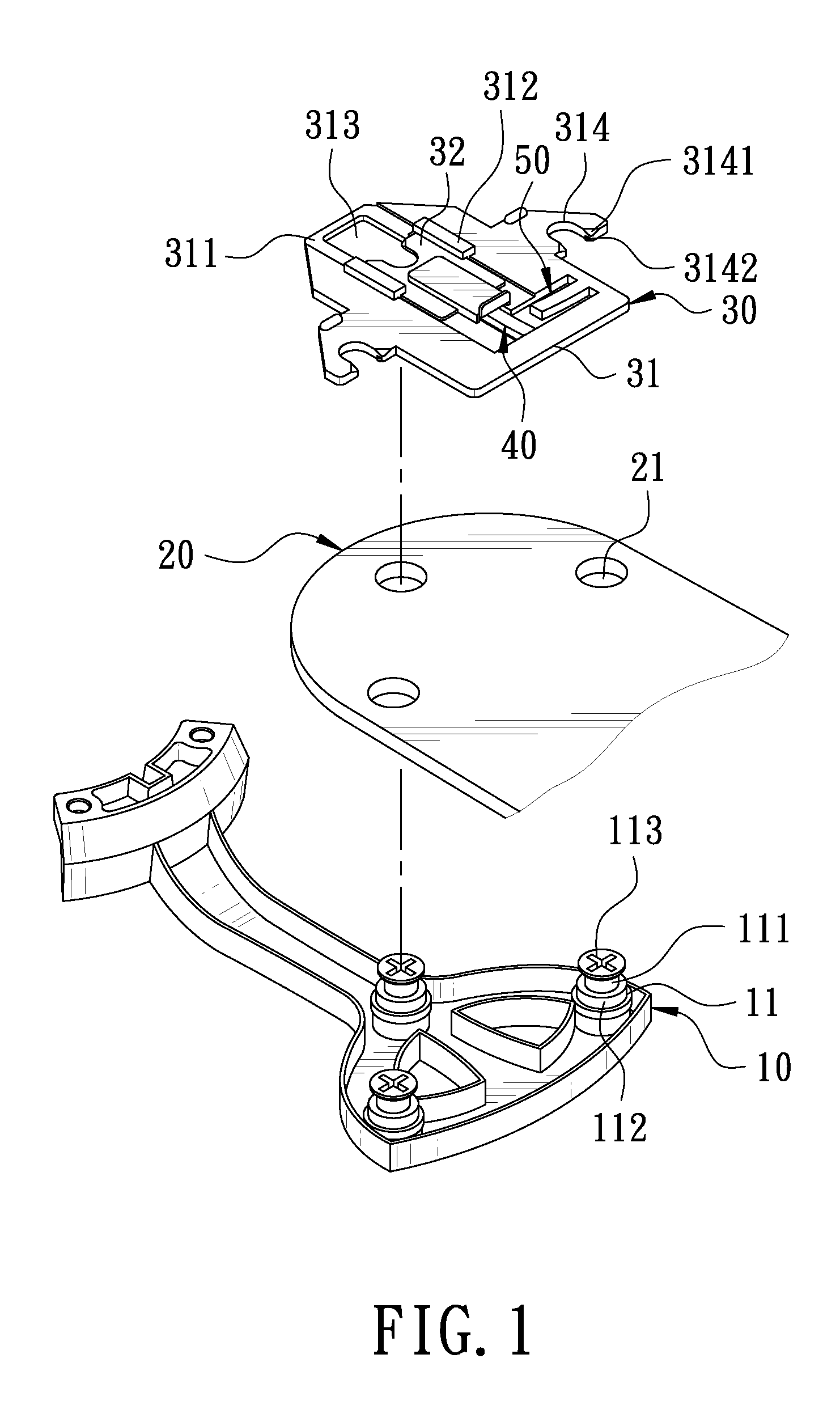
[0015]With reference to FIG. 1 shown as a 3D exploded view of a preferred embodiment of the present invention, a locking device mainly comprises a blade rack 10, a blade 20, and a fixing plate 30. On the blade rack 10, three triangular pillars 11 are formed. Each of the pillars 11 is formed with a screw bolt 111 and a rubber sheath 112 set around the screw bolt 111 to form on the top of pillar 11 a head 113 of which the diameter is larger than that of pillar 11. On the blade 20 opposite to the pillar 11 of blade rack 10, three thru holes 21 are formed and set around the pillar 11 of blade rack 10 and lie below the head 113 of th...


PUM


Abstract

A locking plate fast fastening ceiling fan blades includes a clamp plate. A chute is formed on the clamp plate, where a pushing board is contained. The clamp plate in the chute is provided with a first wedge unit and a thru hole. Thus, when a set of blades is installed on a blade rack of a ceiling fan, only the blade is set around several pillars on the blade rack, the clamp plate of fixing plate is set to locate on the pillar, and a pillar is made to pass through the thru hole. The pushing board of fixing plate is shifted toward the pillar, making the front end of pushing board stay close to the side of pillar and the first wedge unit of clamp plate stay close to the terminal of pushing board for fast and exact completion of fixing of the blade onto the blade rack.

Description

BACKGROUND OF THE INVENTION[0001]1. Field of the Invention[0002]This invention relates to a locking plate fast fastening ceiling fan blades.[0003]2. Description of the Prior Art[0004]In order to prevent the fact that the blades of a conventional ceiling fan is collided to deviate the preset angle of the blades, when the blades are shipped, and thus that the installed ceiling fan causes noise and even wobbles when operating, the body of ceiling fan and a blade rack are in advance installed on the ceiling, and then the several blades are locked onto the blade rack of the body, the effects of easy shipment, preservation, and installation being further achievement.[0005]However, the blade of conventional ceiling fan is definitely long as a rule and a front end of the blade is generally locked; it is not easily installed. In order to solve the defects, a locking device fastening the ceiling fan blades as disclosed in U.S. Pat. No. 6,652,236 is developed in the market. In this disclosure,...

Claims


Application Information

Patent Timeline
IPC IPC(8): F04D29/36
CPCF04D29/34F04D25/088
Inventor WANG, CLIFF
Owner AIR COOL INDAL
Why Eureka
Try Eureka