
Capacitive Touch Sensing Structure and Sensing Method Thereof

a capacitive touch and sensing technology, applied in the field of capacitive touch sensing, can solve the problems of increasing production cost and achieve the effect of accurate results

Active Publication Date: 2010-11-18
MEDIATEK INC
View PDF5 Cites 47 Cited by
  • Summary
  • Abstract
  • Description
  • Claims
  • Application Information

AI Technical Summary

Benefits of technology

[0017]A main object of the present disclosure is to provide a capacitive touch sensing structure and a sensing method thereof, so that a touched position is accurately obtained without increasing extra conducting wires.

Problems solved by technology

Corresponding detection circuit is complex and the number of pins connected to electrodes is increased, leading to increased production cost.

Method used


Image

  • Capacitive Touch Sensing Structure and Sensing Method Thereof
  • Capacitive Touch Sensing Structure and Sensing Method Thereof
  • Capacitive Touch Sensing Structure and Sensing Method Thereof

Examples


first embodiment

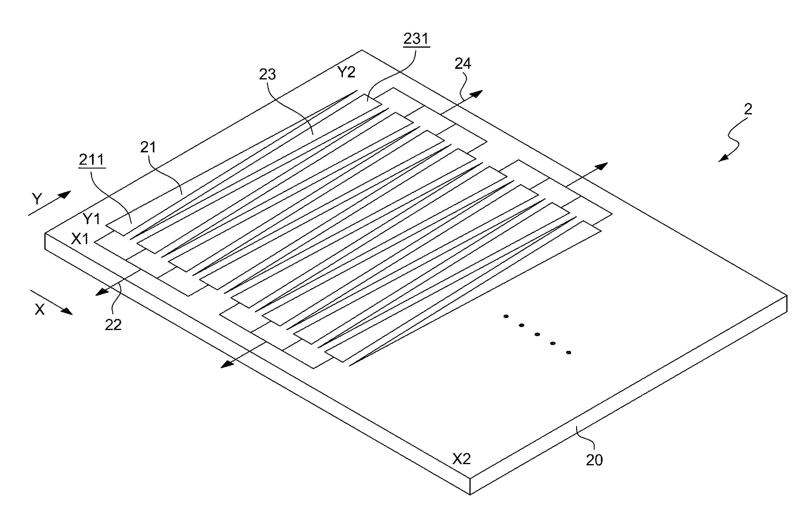
[0032]FIG. 2A shows a capacitive touch sensing structure 2 in accordance with the present disclosure. The sensing structure 2 comprises a substrate 20, a plurality of first electrode groups 21, a plurality of first conducting wires 22, a plurality of second electrode groups 23, and a plurality of second conducting wires 24.

[0033]The substrate 20 can be in shape of a rectangle and comprises a first direction X and a second direction Y. The first direction X directs from a first position X1 to a second position X2, and the second direction Y directs from a first position Y1 to a second position Y2.

[0034]The first electrode groups 21 are arranged in sequence from the first position X1 towards the second position X2 in the first direction X. Each of first electrode groups 21 comprises a plurality of first electrodes 211, which are triangular or trapezoid in shape. Each of the first electrodes has its bottom located at the first position Y1 of the second direction Y of the substrate 20, ...

second embodiment

[0049]FIG. 4A shows a capacitive touch sensing structure 3 in accordance with the present disclosure. The sensing structure 3 comprises a substrate 30, a plurality of first electrode groups 31, a plurality of first conducting wires 32, a plurality of second electrode groups 33, a plurality of second conducting wires 34, a third electrode 35, and a third conducting wire 36.

[0050]The substrate 30, e.g., in shape of a rectangle, comprises a first direction X and a second direction Y. The first direction X directs from a first position X1 to a second position X2, and the second direction Y directs from a first position Y1 to a second position Y2.

[0051]The first electrode groups 31 are arranged in sequence from the first position X1 towards to the second position X2 in the first direction X. Each of the first electrode groups 31 comprises a plurality of first electrodes 311, which are triangular or trapezoid in shape. Each of the first electrodes 311 has its bottom located at the first p...


PUM


Abstract

A capacitive touch sensing structure includes: a substrate; a plurality of first electrode groups arranged from a first position towards a second position in a first direction, wherein each of the first electrode groups includes a plurality of first electrodes extended from a third position towards a fourth position in a second direction; a plurality of first conducting wires each having a plurality of contacts respectively coupled to the first electrodes of each of the first electrode groups; a plurality of second electrode groups arranged from the first position towards the second position in the first direction, wherein each of the second electrode groups includes a plurality of second electrodes extended from the fourth position towards the third position in the second direction and respectively staggering with the first electrode groups; and a plurality of second conducting wires each having a plurality of contacts respectively coupled to the electrodes of each of the second electrode groups.

Description

CROSS REFERENCE TO RELATED PATENT APPLICATIONS[0001]This patent application claims priority from U.S. Provisional Patent Application No. 61 / 178,506 filed on May 15, 2009, which is hereby incorporated in its entirety by reference.TECHNICAL FIELD[0002]The present disclosure relates to capacitive touch sensing, and more particularly, to a capacitive touch sensing structure and a sensing method thereof.BACKGROUND OF THE PRESENT DISCLOSURE[0003]As science and technology continue to develop, touch panels are widely applied to various types of electronic apparatuses. In addition to replacing buttons, use of touch panels generally allow electronic apparatuses to also benefit from enlarged display images.[0004]Common touch panels in general are classified into various types including a resistive type, a capacitive type, an infrared type, and an ultrasonic type, for example. Since a capacitive touch panel includes advantageous features such as being dustproof and scratchproof as well as havin...

Claims


Application Information

Patent Timeline
Patent Type & Authority Applications(United States)
IPC IPC(8): G06F3/042
CPCG06F3/044G06F3/0446G06F3/0448
Inventor PAN, HSUAN-IHUNG, GUO-KIANG
Owner MEDIATEK INC
Features
  • Generate Ideas
  • Intellectual Property
  • Life Sciences
  • Materials
  • Tech Scout
  • Unparalleled Data Quality
  • Higher Quality Content
  • 60% Fewer Hallucinations
Learn More