
Method, apparatus, and program for image processing

a technology of image processing and program, applied in the field of image processing, can solve the problems of poor focus, poor adjustment of focal length, time-consuming method,

Inactive Publication Date: 2005-11-10
FUJIFILM CORP
View PDF17 Cites 62 Cited by
  • Summary
  • Abstract
  • Description
  • Claims
  • Application Information

AI Technical Summary

Benefits of technology

[0014] The present invention has been conceived based on consideration of the above circumstances. An object of the present invention is therefore to provide an image processing method, an image processing apparatus, and an image processing program for achieving a desirable correction effect by enabling appropriate acquisition of information on a blur in a digital photograph image including a part having gradation, without a specific device installed in an imaging device.
[0041] According to the image processing method, the image processing apparatus, and the program of the present invention, the point-like part is detected in the digital photograph image, and the blur information of the digital photograph image is obtained by using the image data of the point-like part. Therefore, the blur information can be obtained without a specific device installed in an imaging device, and the blur information can be obtained properly even in the case where gradation is observed in the digital photograph image.
[0042] Furthermore, in the case where the blur in the digital photograph image has been caused by shake, the information on the direction of the shake is obtained by using the image data of the point-like shape. At the same time, the blur information other than the information on the direction of the shake, such as the information on the width of the blur (that is, a length of the shake, in this case), can be obtained from the data of the entire digital photograph image based on the information on the direction of the shake found from the image data of the point-like part by letting the length of the shake be represented by an average edge width in the entire digital photograph image in the direction of the shake represented by the information on the direction of the shake. In this manner, the information on the direction of the shake can be obtained properly. In addition, the information other than the direction of the shake, such as the information on the width of the blur, can be found more accurately, since an amount of data is enriched for finding the information other than the direction of the shake.

Problems solved by technology

As causes of blurry images are listed poor focus due to poor adjustment of focal length and camera shake (hereinafter simply referred to as shake) caused by movement of hands of a photographer.
However, this method is time-consuming, since the procedure needs to be carried out repeatedly.
However, since a mobile phone is not produced as a dedicated photography device, a mobile phone embedded with a digital camera is ergonomically unstable to hold at the time of photography.
Furthermore, since a phone camera does not have a flash, a shutter speed is slower than an ordinary digital camera.
However, minor camera shake cannot be confirmed on a monitor, and becomes noticeable only after printing of an image.
However, how to downsize mobile phones is one of key points in competition for manufacturers of mobile phones, in addition to performance and cost thereof.
Therefore, installation of a device for obtaining information on direction and length of shake in a phone camera is not realistic.
Therefore, the method in U.S. Patent Application Publication No. 20030002746 cannot be applied to a phone camera.
The method described in Japanese Unexamined Patent Publication No. 7(1995)-121703 is also problematic in terms of processing efficiency, since the method needs repetition of the procedure comprising degradation function setting, restoration, evaluation, and degradation function setting again.
This method for obtaining the information on a blur in an image by analysis of a state of an edge in the image results in improper analysis in the case of presence of a gradation-like blurry edge in the image, which is also problematic.

Method used


Image

  • Method, apparatus, and program for image processing
  • Method, apparatus, and program for image processing
  • Method, apparatus, and program for image processing

Examples


Embodiment Construction

[0076] Hereinafter, embodiments of the present invention will be described with reference to the accompanying drawings.

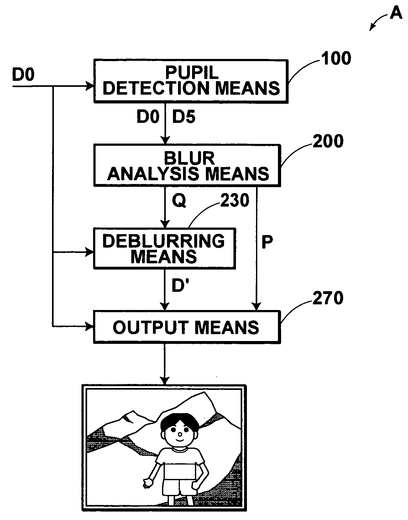
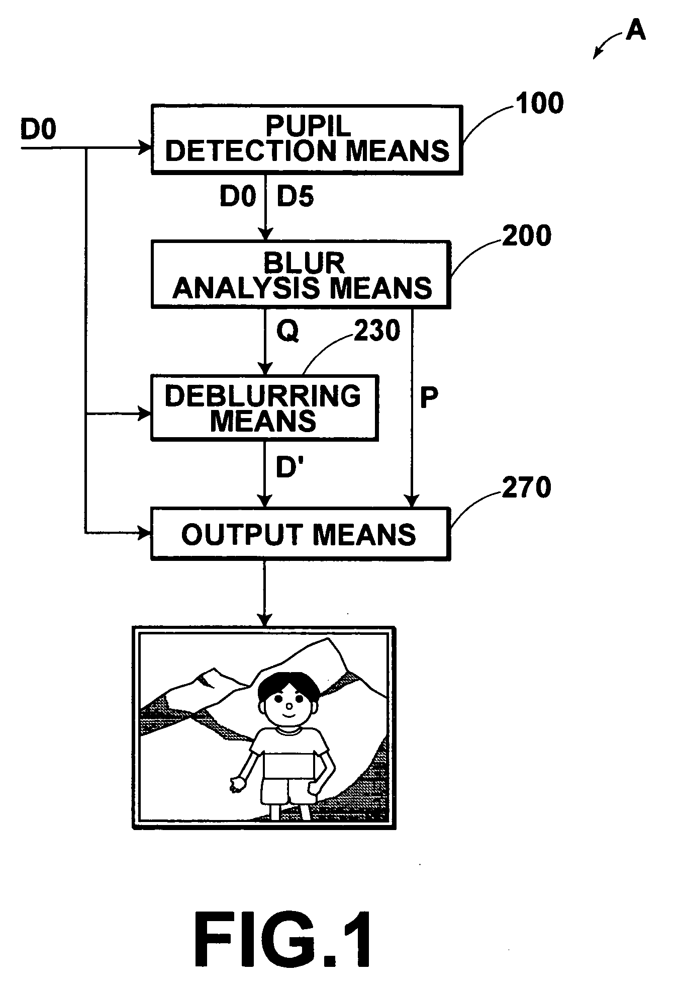
[0077]FIG. 1 is a block diagram showing the configuration of an image processing system A of a first embodiment of the present invention. The image processing system A in the first embodiment carries out deblurring processing on a digital photograph image (hereinafter simply referred to as an image) input thereto, and prints the image. The deblurring processing is carried out by executing a deblurring program read out to a storage device by using a computer (such as a personal computer). The deblurring program is stored in a recording medium such as a CD-ROM or distributed via a network such as the Internet to be installed in the computer.

[0078] Since image data represent an image, the image and the image data have the same meaning in the description below.

[0079] As shown in FIG. 1, the image processing system A in this embodiment has pupil detection means 100, b...


PUM


Abstract

Blur information on an image is found appropriately. Blur analysis means calculates a degree of blur and a direction of blur by using pupil images of the image obtained by pupil detection means, and judges whether or not the image is a blurry image. For the image having been judged as a blurry image, a degree of shake and a width of blur are calculated from the pupil images, and the degree of blur, the width of blur, the direction of blur, and the degree of shake obtained from the pupil images are output as the blur information of the image to deblurring means. The deblurring means corrects the image based on the blur information, and obtains a corrected image.

Description

BACKGROUND OF THE INVENTION [0001] 1. Field of the Invention [0002] The present invention relates to an image processing method and an image processing apparatus for obtaining blur information on digital photograph images. The present invention also relates to a program for causing a computer to execute the image processing method. [0003] 2. Description of the Related Art [0004] Digital photograph images are obtained by photography with a digital still camera (DSC) or by photoelectrically reading photograph images recorded on a photographic film such as a negative film and a reversal film with a reading device such as a scanner, and printed after having been subjected to various kinds of image processing thereon. Deblurring processing for correcting a blur in a blurry image is one type of such image processing. [0005] As causes of blurry images are listed poor focus due to poor adjustment of focal length and camera shake (hereinafter simply referred to as shake) caused by movement o...

Claims


Application Information

Patent Timeline
Patent Type & Authority Applications(United States)
IPC IPC(8): G03B17/00
CPCG03B17/00G06T5/004G06T2207/20081G06T2207/20148H04N5/23254G06T2207/30201H04N5/217H04N5/23219H04N5/23248G06T2207/20201G06T7/136H04N23/81H04N23/611H04N23/6811H04N23/68G06T7/11G06T5/75
Inventor KITAMURA, YOSHIRO
Owner FUJIFILM CORP
Learn More