Infrastructure monitoring devices, systems, and methods

a monitoring device and infrastructure technology, applied in the field of infrastructure monitoring devices, systems and methods, can solve the problems of allowing problems to go unchecked for long periods of time, wasting energy and time, and wasting resources on maintenance and repair,

Active Publication Date: 2010-11-25
MUELLER INT LLC
View PDF112 Cites 160 Cited by
  • Summary
  • Abstract
  • Description
  • Claims
  • Application Information

AI Technical Summary

Problems solved by technology

Such systems are usually complex infrastructures and include but are not limited to water distribution, gas distribution, electricity distribution, waste management, traffic control, fire departments, police departments, and emergency response departments.
This is slow, labor-intensive process can lead to overlooked problems.
Furthermore, preferred aspects of the system may only be evaluated irregularly or infrequently, thereby allowing a problem to go unchecked for long periods of time.
For example, a leak in a water main may cost a water company a significant amount of money in lost water, energy usage, and chemical treatment, particularly if the leak is not discovered for a long period of time.
Furthermore, a leak can lead to underground structural erosion.
Another problem and disadvantage associated with current systems is the lack of property rights sufficient to maintain a network of monitors and device controllers capable of creating a transmission infrastructure that can adapt to multiple monitors and controllers and form an information network for providing information about the system to the utility monitoring the network.
Furthermore, an issue in one system may cause an issue in another system.
However, current systems are not interoperable.

Method used


Image

  • Infrastructure monitoring devices, systems, and methods
  • Infrastructure monitoring devices, systems, and methods
  • Infrastructure monitoring devices, systems, and methods

Examples


examples

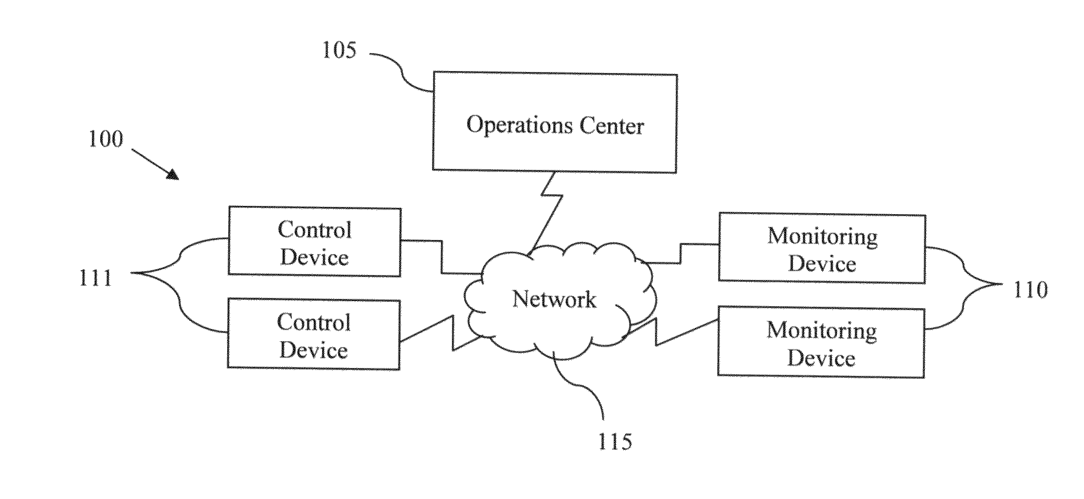
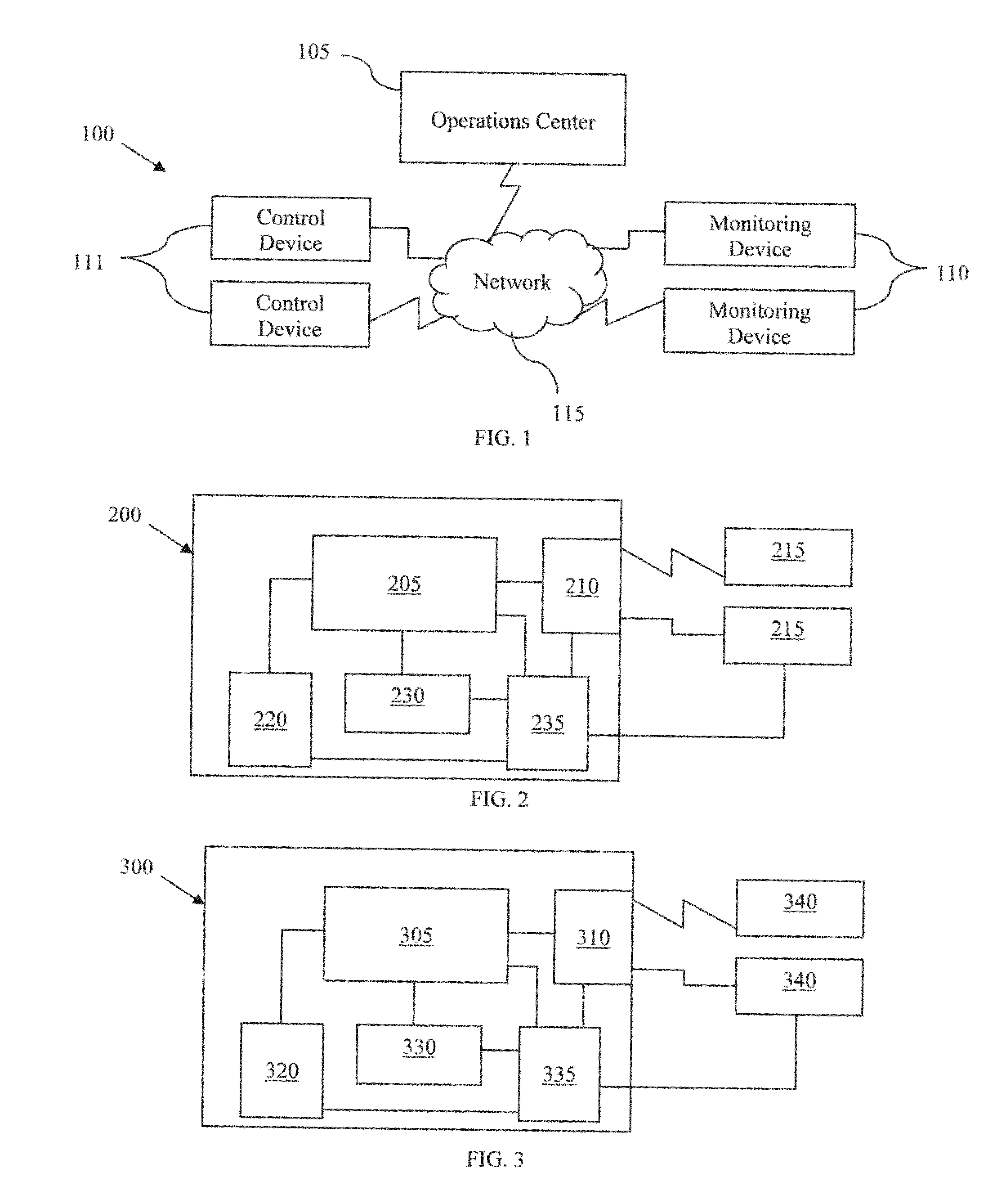
[0071]A system of the invention is monitoring a water distribution infrastructure. The system is used to automatically control the water pressure within the system. Such a system includes a number of water meters disbursed throughout the infrastructure relaying real time use information to a control center. Upon a determination by the operations center that there is low usage of the system (e.g. at night) based on information received by a predetermined number of the water meters, the operations center causes pumps supplying pressure within the system to reduce or cease pumping. Thereby cutting down on the electricity used by the pumps while maintaining enough pressure throughout the infrastructure to satisfy any water needs. The determination to reduce or cease pumping can be also based on information received from pressure sensors disbursed throughout the infrastructure. For example, if the pressure within the infrastructure exceeds a threshold value, the operations center causes ...


PUM


Abstract

An infrastructure monitoring system and method that comprises multiple communications devices. At least one communications device is coupled to an element of the infrastructure.

Description

REFERENCE TO RELATED APPLICATIONS[0001]This application claims priority to U.S. provisional application Ser. No. 61 / 180,600 filed May 22, 2009, entitled “WATER SUPPLY INFRASTRUCTURE MONITORING SYSTEM AND METHOD,” which is hereby specifically and entirely incorporated by reference.BACKGROUND[0002]1. Field of the Invention[0003]The invention is directed to devices, systems, and methods of monitoring and controlling an infrastructure such as, but not limited to the supply and use of commercial, industrial or residential water, gas and / or electric, and, in particular, to devices, methods, and systems for monitoring and controlling a municipality and alerting a user to potential faults and actions required.[0004]2. Background of the Invention[0005]Municipalities administer and / or outsource numerous utility and safety systems within each municipality. Such systems are usually complex infrastructures and include but are not limited to water distribution, gas distribution, electricity distr...

Claims


Application Information

Patent Timeline
Patent Type & Authority Applications(United States)
IPC IPC(8): G08B21/00G08B1/08
CPCG05B2219/13H04Q9/00H04Q2209/47H04Q2209/43G08C17/02H04Q2209/823E03B9/06G08B25/006G08B25/10H04Q2209/25G05B2223/06Y10T137/5468
Inventor HYLAND, GREGORY E.KEEFE, ROBERT PAULZAKAS, MARIETTA EDMUNDSBARKER, CLAYTON ROBERT
Owner MUELLER INT LLC
Why Eureka
Try Eureka