Precision Total Knee Arthroplasty

a tibial tray and a technology for knees, applied in the field of orthopedic surgery, can solve the problems of shortened useful life, virtually all conventional tibial tray inserts undergo some degree of backside wear, and the inability to provide a secure fit of the polyethylene tibial tray insert onto the upper surface of the underlying tibial tray

Inactive Publication Date: 2010-11-25
UNGER ANTHONY S
View PDF0 Cites 38 Cited by
  • Summary
  • Abstract
  • Description
  • Claims
  • Application Information

AI Technical Summary

Benefits of technology

The patent describes a new type of knee joint replacement called a modular titanium implant. This implant has two main parts: a plastic part made with a special process and a metal plate for attachment to bone marrow cells. There are also some small holes on the surface of this design that can hold an instrument used to separate them during surgery. Overall, this innovation makes it easier to replace damaged knees with better quality components.

Problems solved by technology

The technical problem addressed in this patent text is the need for a modular tibial prosthetic device that securely attaches the tibial tray insert onto the upper surface of the tibial tray to eliminate micro-motion and the deleterious effects of backside wear. Additionally, the device should be easily customizable and allow for the replacement of worn tibial tray inserts when necessary.

Method used


Image

  • Precision Total Knee Arthroplasty
  • Precision Total Knee Arthroplasty
  • Precision Total Knee Arthroplasty

Examples


Embodiment Construction

[0026]Detailed embodiments of the present invention are disclosed herein; however, it is understood that the following description and each of the accompanying figures are provided as being exemplary of the invention, which may be embodied in various forms without departing from the scope of the claimed invention. Thus; the specific structural and functional details provided in the following description are non-limiting, but serve merely as a basis for the invention as defined by the claims provided herewith. The device described below can be modified as needed to conform to further development and improvement of materials without departing from the inventor's concept of the invention as claimed.

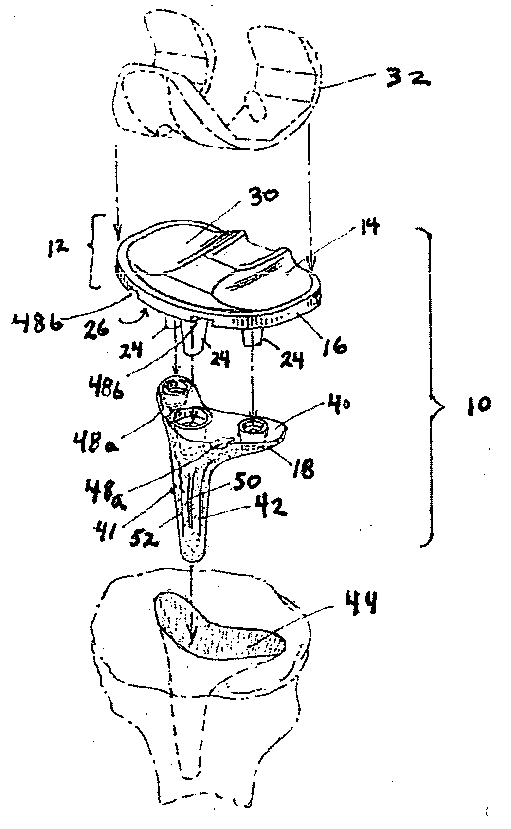
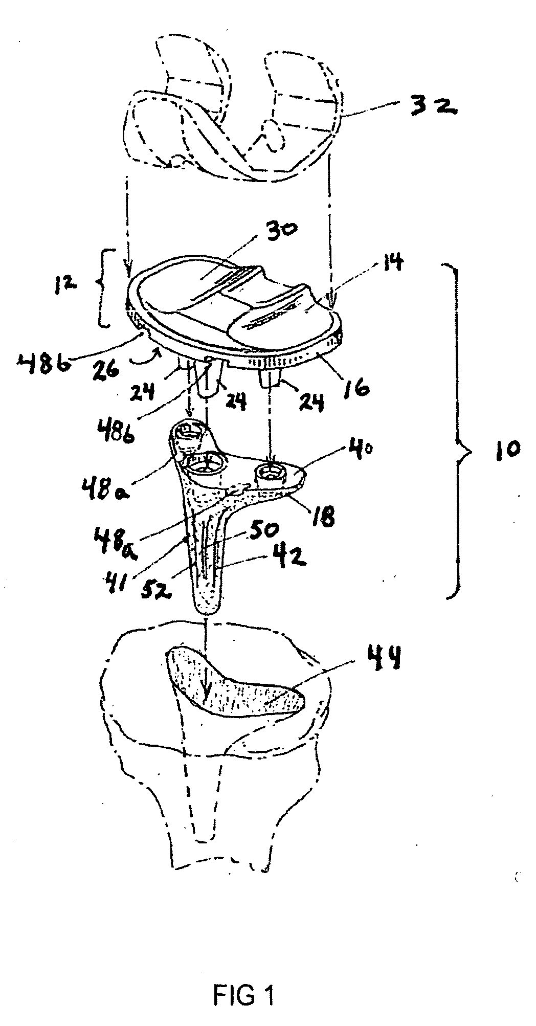
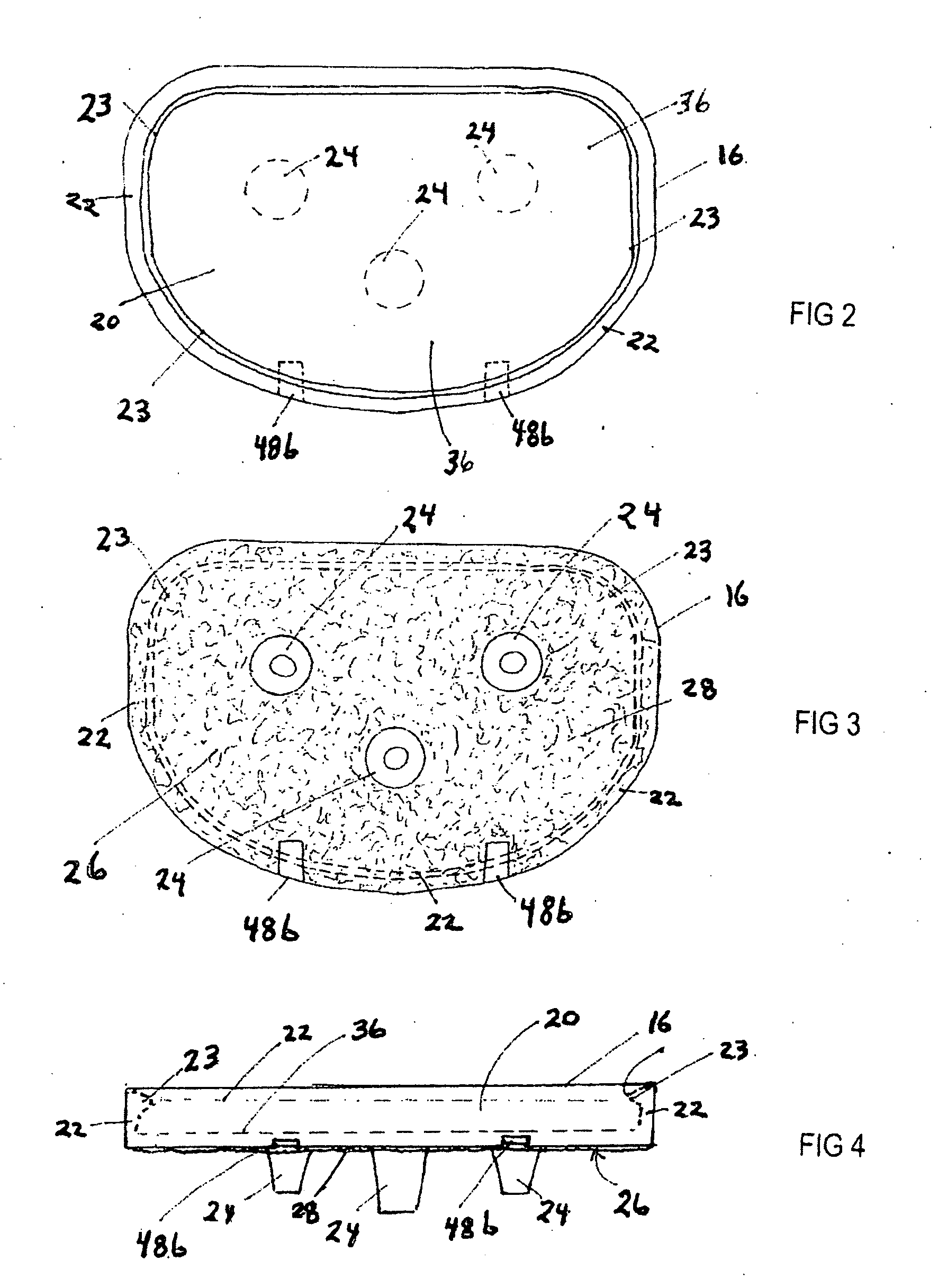
[0027]The novel modular tibial prosthesis device, as generally shown at 10 in FIG. 1, includes a tibial tray module 12, which is formed by direct pressure molding of an articulation component 14 into a tibial tray component 16. The tibial tray module 12, unlike conventional tibial prosthetic...


PUM

PropertyMeasurementUnit
Sizeaaaaaaaaaa

Abstract

Provided is a novel modular tibial prosthesis that includes an articulation component formed by direct pressure molding of a resin composition into a tibial tray component to provide a factory formed resin-metal composite structure a tibial tray module. The tibial tray component being capable of releasable attachment to an underlying keel element. A method of manufacture of the tibial prosthesis is also disclosed.

Description


Claims


Application Information

Patent Timeline
Owner UNGER ANTHONY S
Why Eureka
Try Eureka