Intrauterine device

Active Publication Date: 2010-12-02
YALE UNIV +1
View PDF14 Cites 23 Cited by
  • Summary
  • Abstract
  • Description
  • Claims
  • Application Information

AI Technical Summary

Benefits of technology

[0010]It is a further object of the present invention to provide a method for preventing conception within the uterine cavity including the step of delivering an intrauterine device into the uterine cavity for positioning between lateral walls of the uterine cavity. The intrauterine device includes an elongated member with a first end and second end, and a first plug member secure

Problems solved by technology

There is ongoing controversy regarding the mechanisms of action of IUDs in humans.
Another problem with IUDs is expulsion from the uterus and subsequent unwanted pregnancy.
This condi

Method used


Image

  • Intrauterine device
  • Intrauterine device
  • Intrauterine device

Examples


Embodiment Construction

[0031]The detailed embodiments of the present invention are disclosed herein. It should be understood, however, that the disclosed embodiments are merely exemplary of the invention, which may be embodied in various forms. Therefore, the details disclosed herein are not to be interpreted as limiting, but merely as the basis for the claims and as a basis for teaching one skilled in the art how to make and / or use the invention. Since various embodiments are disclosed herein, similar reference numerals have been employed throughout the present disclosure when referring to similar elements in the various embodiments and where such use of similar references numerals is deemed appropriate.

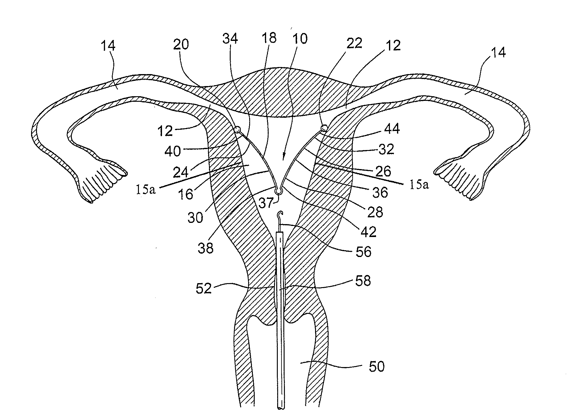
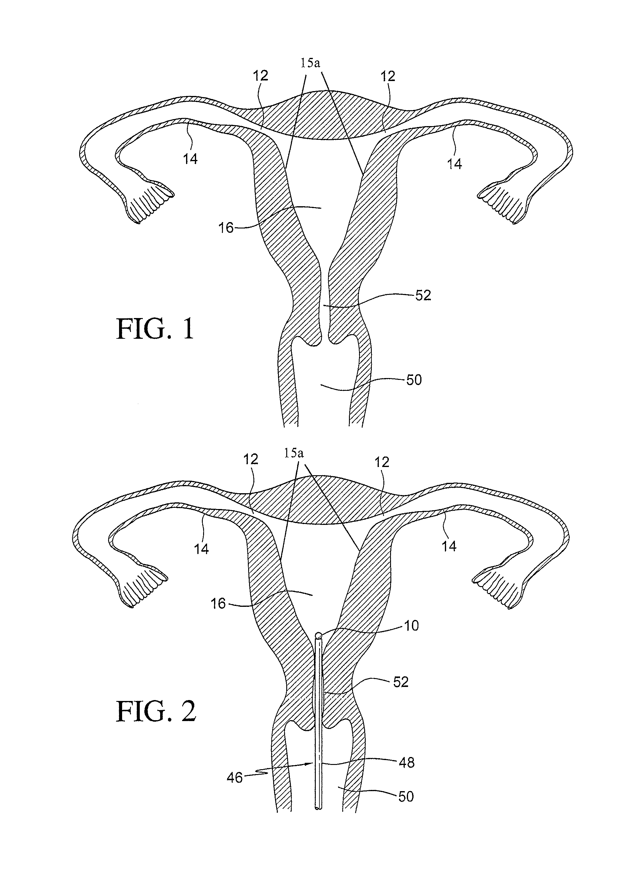
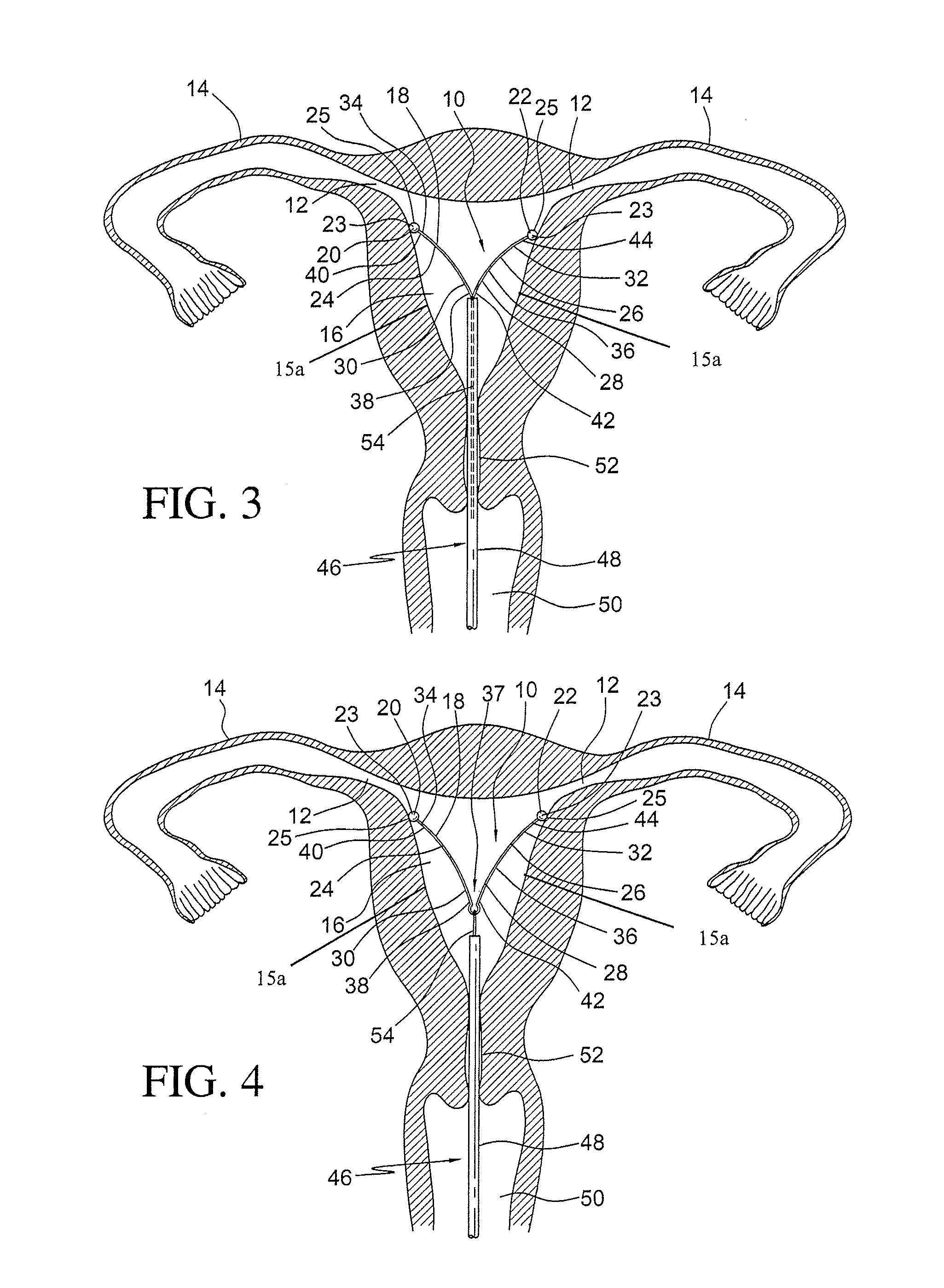
[0032]With reference to the various figures, an intrauterine device 10 in accordance with a preferred embodiment of the present invention is disclosed that will actively bear against the lateral walls 15a of the uterine cavity 16 using the shape of the uterine cavity 16 as a guide to the proper positionin...


PUM


Abstract

An intrauterine device for applying pressure to the walls of the uterine cavity includes a resilient body having an elongated member which includes a first end and a second end which are resiliently biased away from each other. The first end of the elongated member includes a first leg having a first end and a second end. The second end of the elongated member includes a second leg having a first end and a second end. A connection member is positioned between the first end of the first leg and the first end of the second leg. A first plug member is secured at the second end of the first leg and a second plug member is secured at the first end of the second leg. The first and second plug members are shaped and dimensioned for bearing against the walls of the uterine cavity as the elongated member spreads outwardly with the first end and the second end moving apart. A method for preventing conception within the uterine cavity is also disclosed.

Description

CROSS REFERENCE TO RELATED APPLICATIONS[0001]This application is a continuation-in-part of U.S. patent application Ser. No. 12 / 353,770, filed Jan. 14, 2009, entitled “INTRAUTERINE FALLOPIAN TUBE OCCLUSION DEVICE”, which is currently pending, the '770 application claims the benefit of U.S. Provisional Application Ser. No. 61 / 006,454, filed Jan. 15, 2008, entitled “INTRAUTERINE FALLOPIAN TUBE OCCLUSION DEVICE”, and the '770 application is a continuation-in-part of U.S. patent application Ser. No. 11 / 892,560, filed Aug. 23, 2007, entitled “INTRAUTERINE FALLOPIAN TUBE OCCLUSION DEVICE”, which is now U.S. Pat. No. 7,621,276, which is continuation-in-part of U.S. patent application Ser. No. 11 / 884,027, filed Aug. 9, 2007, entitled “INTRAUTERINE FALLOPIAN TUBE OCCLUSION DEVICE AND METHOD FOR USE”, which is now U.S. Pat. No. 7,669,601, which is the National Stage of International Application No. PCT / US2006 / 005245, filed Feb. 15, 2006, entitled “INTRAUTERINE FALLOPIAN TUBE OCCLUSION DEVICE A...

Claims


Application Information

Patent Timeline
IPC IPC(8): A61F6/14
CPCA61F6/142A61F6/20A61F6/18H04R5/02B60R11/0217H04R1/026H04R1/24H04R1/323H04R2499/13
Inventor TAL, MICHAEL G.GUTELIUS, PATRICK N.DEBISSCHOP, MARK J.SHIKHMAN, OLEGPATRIZIO, PASQUALE
Owner YALE UNIV
Why Eureka
Try Eureka