Shaft Holding System for Cryogenic Pumps or Expanders

a technology of expander or pump shaft and holding system, which is applied in the direction of mechanical equipment, hydraulic drum brakes, hoisting equipment, etc., can solve the problems of introducing stress to the shaft bearings, damaging the shaft, and damaging the shaft of an expander or pump

Inactive Publication Date: 2010-12-02
ELLIOTT CO
View PDF12 Cites 10 Cited by
  • Summary
  • Abstract
  • Description
  • Claims
  • Application Information

AI Technical Summary

Problems solved by technology

There are problems which can damage a shaft of an expander or a pump during standstill conditions.
For example, reverse flow can force the shaft to rotate in reverse, potentially damaging the shaft and introducing stress to the shaft bearings.
An unstable foundation can also make the shaft of an expander or a pump rotate.
Movement in floating platforms can cause the pump or expander to move around, which can cause the shaft of the pump or expander to get damaged.
In floating storage and regasification units that are permanently moored offshore, weather conditions can result in significant movement due to ocean conditions.
For example, if a ship motion constantly changes by pitching and rolling, this can make an expander or pump installed in a vessel, or on a floating storage tank, receive continuous side forces that can damage the shaft.

Method used


Image

  • Shaft Holding System for Cryogenic Pumps or Expanders
  • Shaft Holding System for Cryogenic Pumps or Expanders
  • Shaft Holding System for Cryogenic Pumps or Expanders

Examples


Embodiment Construction

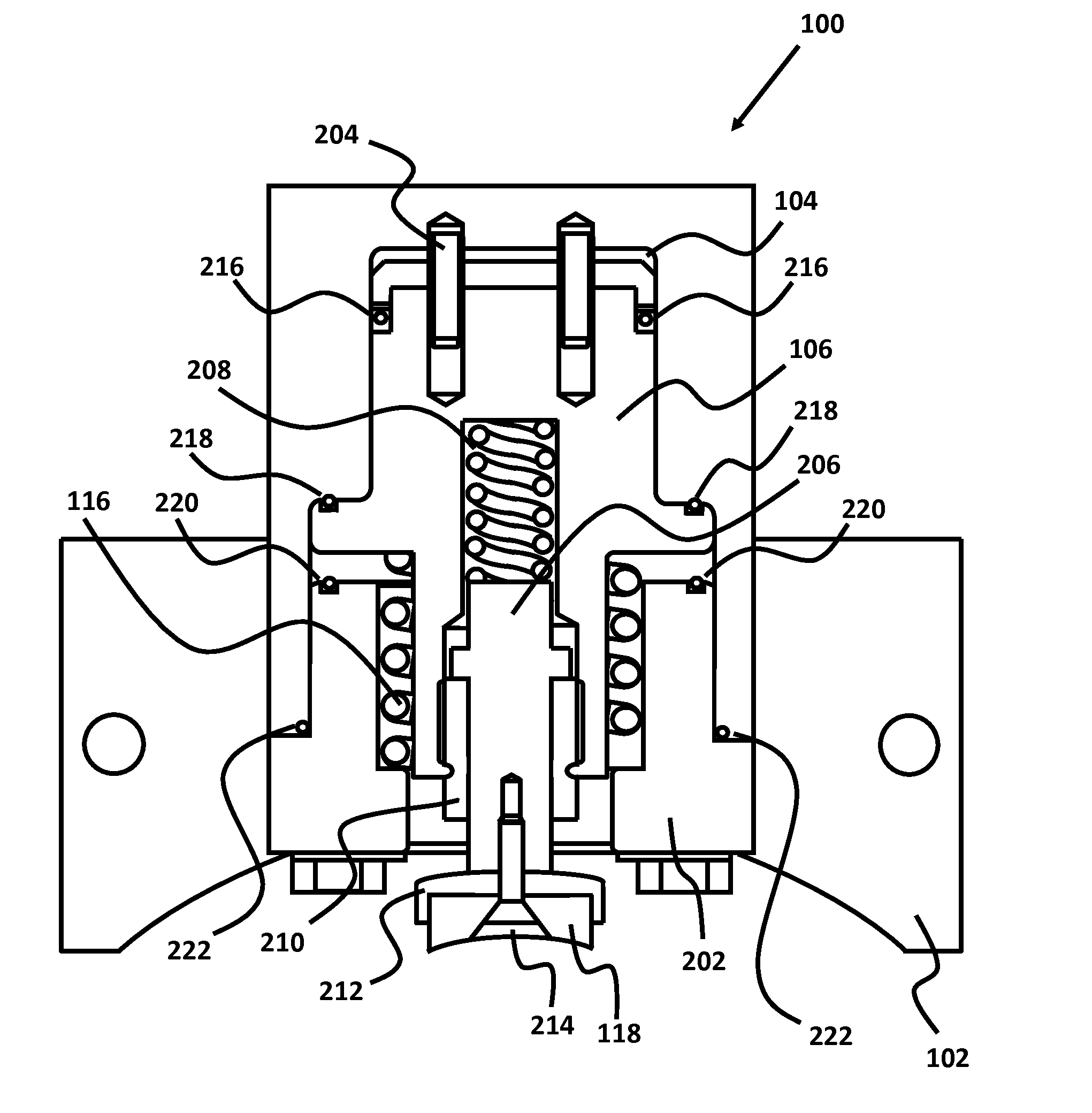
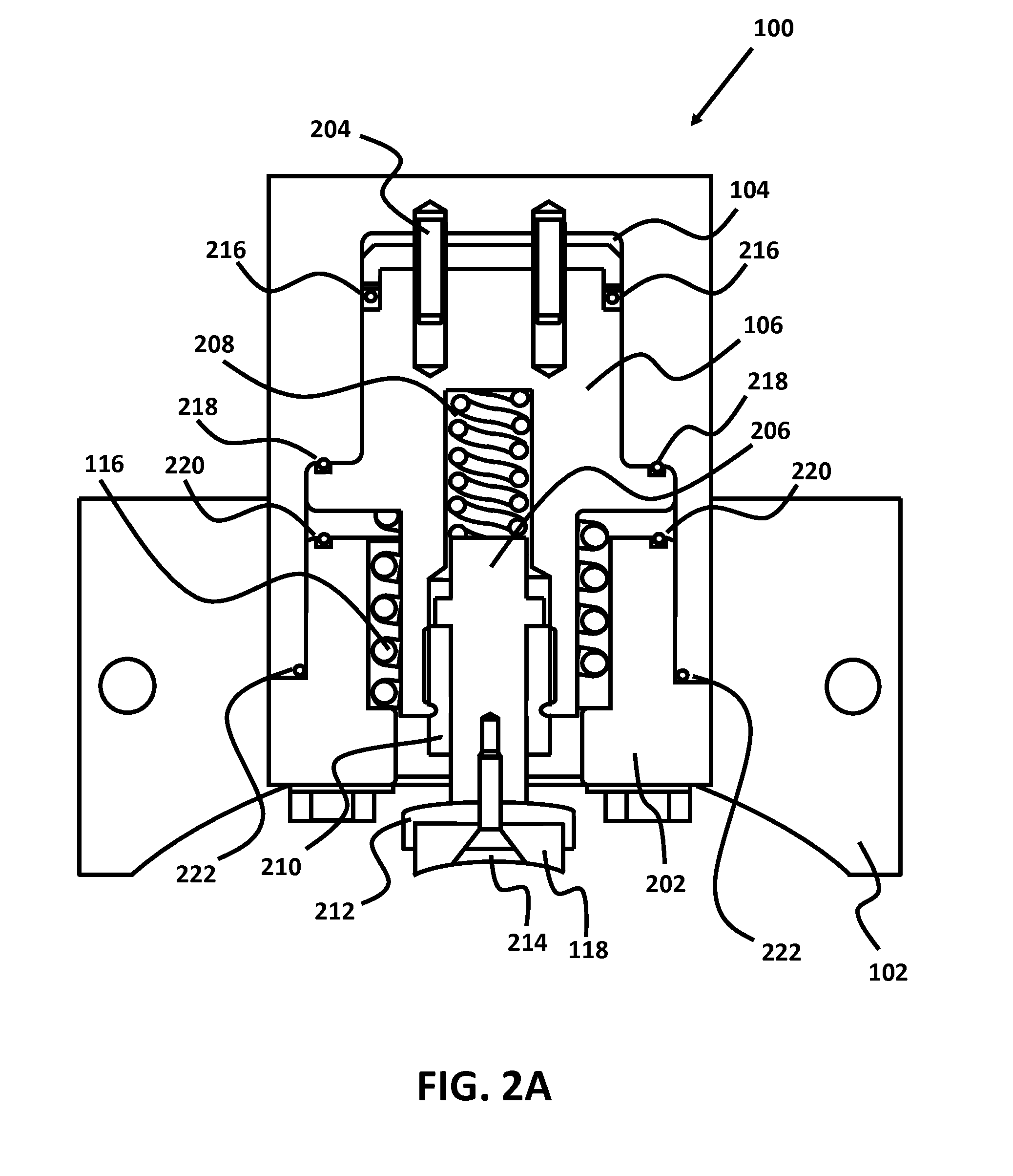
[0010]A shaft holding system consisting of two or more brake assemblies surrounding the shaft of turbomachinery. Turbomachinery generally refers to machines that transfer energy from the processing of a fluid or gas using some type of turbine. From herein, the terms “turbomachinery” and “turbomachines” will be used to refer to turbines, expanders, compressors, fans, or pumps.

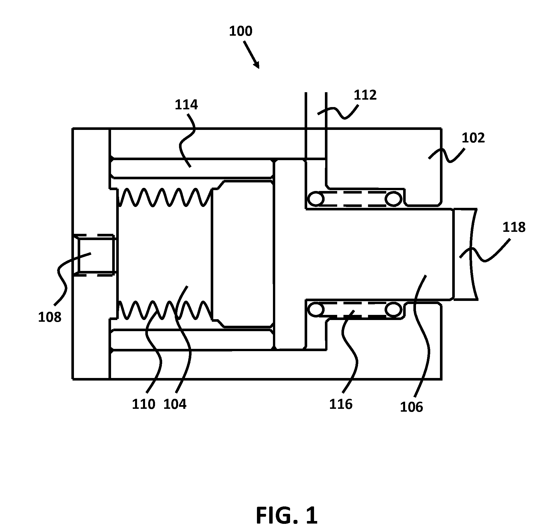
[0011]Each brake assembly consists of one or more hydraulic brakes. In operation, pressure is introduced into a bellows chamber of the brake, which exerts force on a piston. The piston applies force to a brake pad, which forces the brake pads to be pushed against the shaft of the expander, the pump, or other structure. Face seals are used to prevent pressure from escaping around the piston.

[0012]Turbomachines with two or more shafts can use a set of brakes for each of the two or more shafts. For example, in a turbine with a first shaft and a second shaft, where torque from the first shaft is transferred to the s...


PUM


Abstract

A shaft holding system for cryogenic pumps or expanders comprising of a set of hydraulic brakes surrounding the shaft of turbomachinery. Fluid or gas is introduced into the bellows chamber of a brake assembly. The bellows chamber expands due to the increase in pressure, thus exerting a force on the piston of the brake assembly. The piston in turn exerts a force on a brake rod, which pushes a brake pad attached to the end of the brake rod against the shaft. A feed line supplies fluid or gas to the hydraulics of the brake assembly. Two or more brakes can be used to secure the shaft of the turbomachine. A turbomachine including more than one shaft can use a set of brakes for each shaft of the turbomachine.

Description

CROSS-REFERENCES TO RELATED APPLICATIONS[0001]This application claims priority from provisional patent application Ser. No. 61 / 217,201, filed May 26, 2009, which is hereby incorporated herein by reference in its entirety to be considered part of this specification.BRIEF DESCRIPTION OF THE INVENTION[0002]A shaft holding system for cryogenic pumps or expanders comprising a set of hydraulic brakes surrounding the shaft of a turbomachine. Fluid or gas is introduced into the bellows chamber of a brake assembly. The bellows chamber expands due to the increase in pressure, thus exerting a force on the piston of the brake assembly. The piston in turn exerts a force on a brake rod, which pushes a brake pad attached to the end of the brake rod against the shaft. A feed line supplies fluid or gas to the hydraulics of the brake assembly. Two or more brakes can be used to secure the shaft of the turbomachine. A turbomachine including more than one shaft can use a set of brakes for each shaft of ...

Claims


Application Information

Patent Timeline
Patent Type & Authority Applications(United States)
IPC IPC(8): F16D65/32F16D65/28
CPCF16D65/14F16D2121/12F16D2121/02
Inventor KAMIO, KEIJUN
Owner ELLIOTT CO
Why Eureka
Try Eureka