
Adjustable support device

Inactive Publication Date: 2010-12-02
CHUANG MIN LON
View PDF6 Cites 25 Cited by
  • Summary
  • Abstract
  • Description
  • Claims
  • Application Information

AI Technical Summary

Benefits of technology

[0009]A second objective of the present invention is that a threaded rod is risen or descended for moving the casings. With a pulley, the support is adjusted synchronously for its length. This is labor-saving for the user to adjust the length of the support.
[0010]A third objective of the present invention is that the threaded rod is screwed to a nut. The threaded rod and the nut provide a supporting force to bear the weight of the support, preventing the threaded rod from sliding down. The casings are limited to slide by themselves.

Problems solved by technology

This is labor-saving for the user to adjust the length of the support.

Method used


Image

  • Adjustable support device
  • Adjustable support device
  • Adjustable support device

Examples


Embodiment Construction

[0022]Embodiments of the present invention will now be described, by way of example only, with reference to the accompanying drawings.

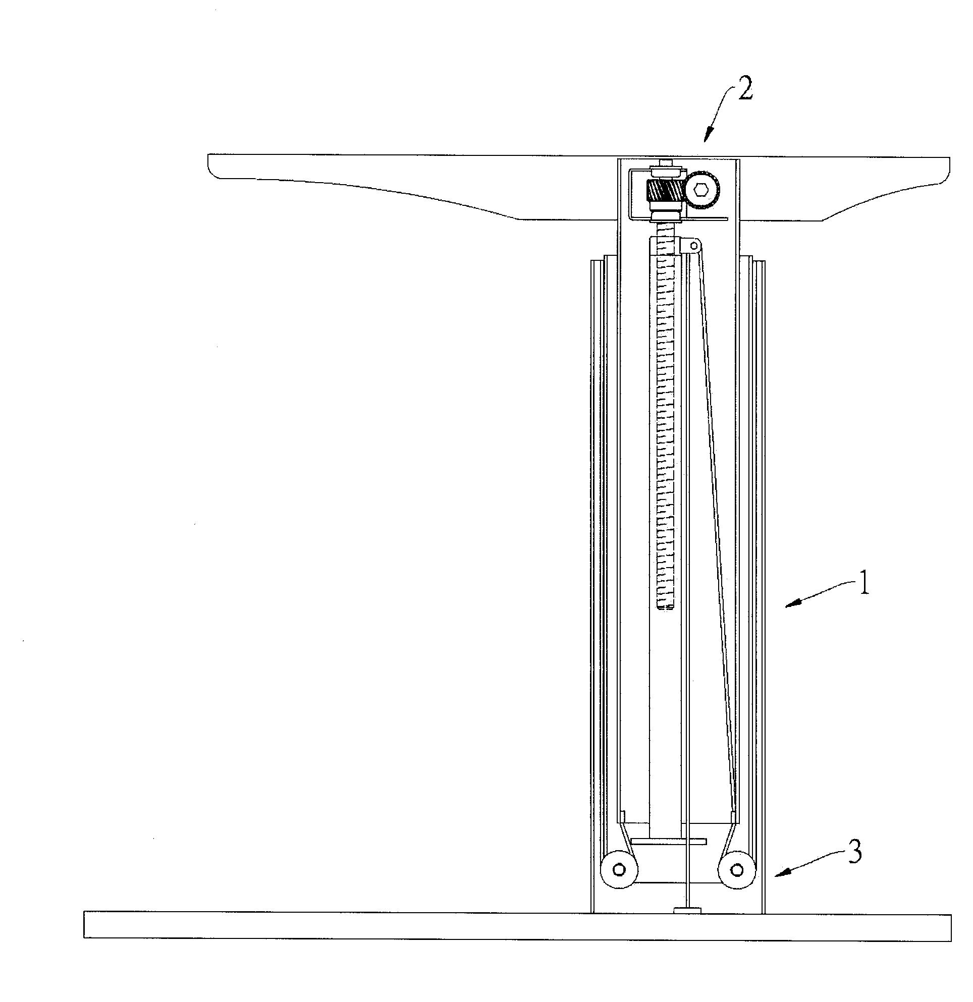
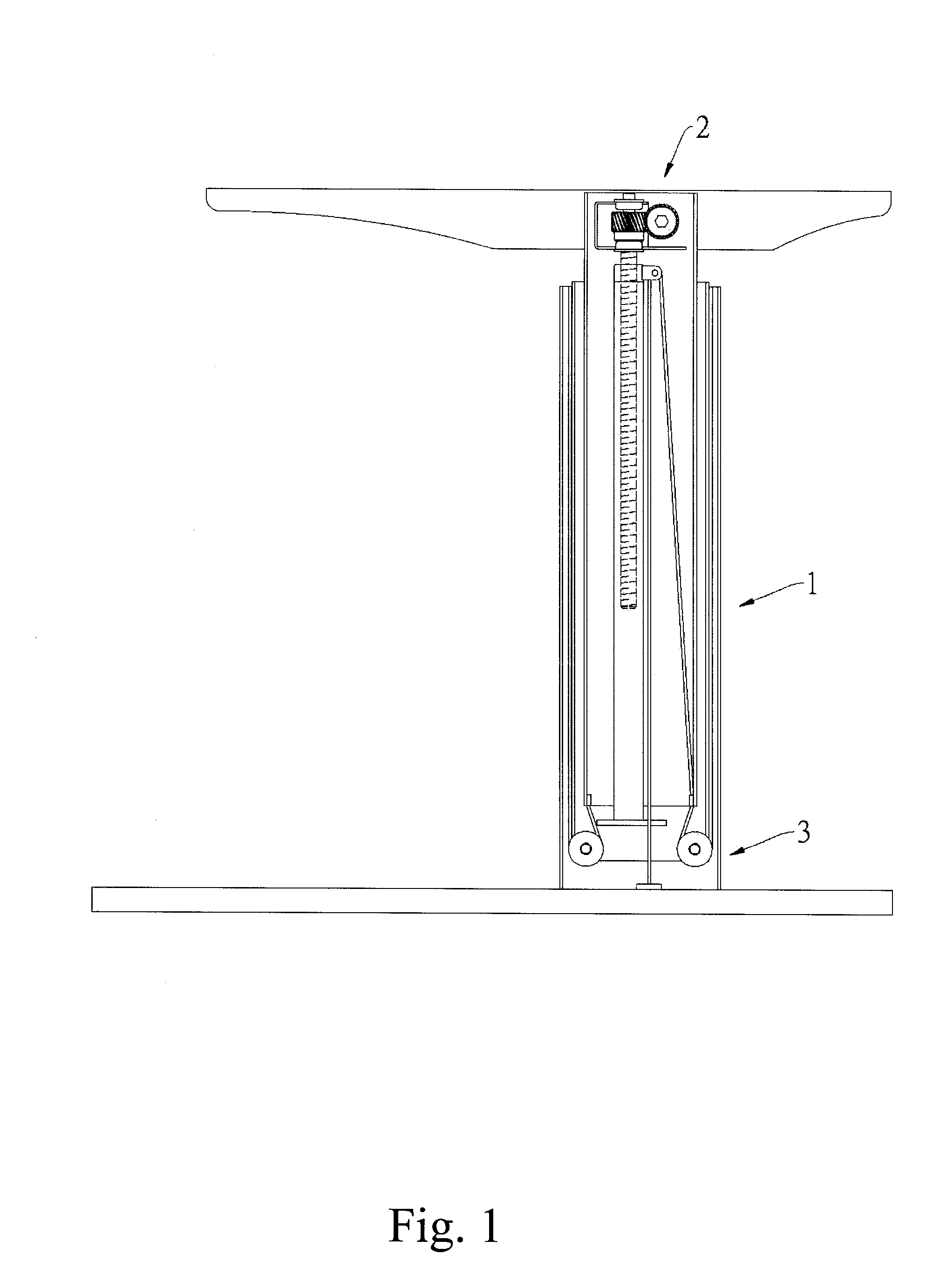
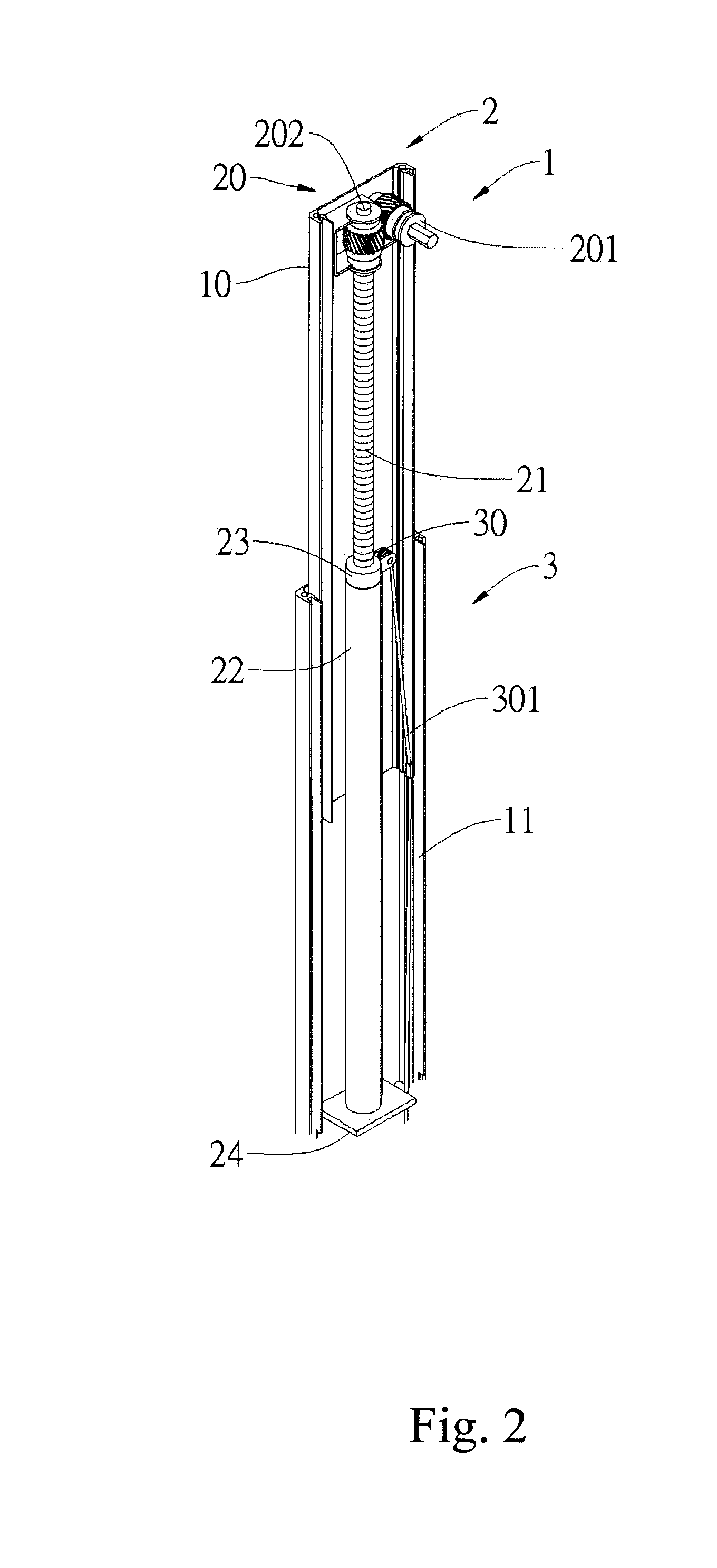
[0023]As shown in FIGS. 1 and 2, an adjustable support device according to a first preferred embodiment of the present invention comprises a support 1, a lift mechanism 2, and at least a pulley unit 3. The support 1 comprises a first casing 10 and a second casing 11 which are slidably connected to each other. The lift mechanism 2 is disposed in the first casing 10 and the second casing 11. The pulley unit 3 is also disposed in the first casing 10 and the second casing 11. The pulley unit 3 comprises at least a first pulley 30 and a first transmission belt 301. The first pulley 30 is connected to the lift mechanism 2. The first transmission belt 301 has a first end connected to the first casing 10 and a second end inserted through the first pulley 30 and connected to the second cashing 11. The lift mechanism 2 comprises a gear unit 20, a threaded rod 2...


PUM


Abstract

An adjustable support device includes a support, a lift mechanism, and a pulley unit. The support includes at least two casings which are slidably connected with each other so as to adjust the length of the support. The lift mechanism includes a threaded rod screwed into a nut for changing the distance between the casings. The pulley unit is adapted for driving the casings. The present invention provides a labor-saving effect for operation.

Description

BACKGROUND OF THE INVENTION[0001]1. Field of the Invention[0002]The present invention relates to an adjustable support device, and more particularly to a support in conjunction with a lift mechanism and a pulley unit to move at least two casings of the support with each other.[0003]2. Description of the Prior Art[0004]Taiwanese Patent No. M284511 discloses a furniture elevator structure, which comprises a screw and a nut for rising and descending. It is necessary to use a longer screw for adjusting a higher position of the elevator. The adjusting speed is subject to the threads of the screw. When the density of the threads is high, the adjusting speed will be slow. But, it is able to support a heavier object. When the density of the threads is low, the adjusting speed will be fast. But, the supporting force of the screw and the nut is low. It is unable to support a heavier object. In addition, the longer screw needs more working procedures. This is not easy to lower the cost. The us...

Claims


Application Information

Patent Timeline
IPC IPC(8): F16M11/26
CPCB66F3/08A47B9/00
Inventor CHUANG, MIN-LON
Owner CHUANG MIN LON
Learn More