Method and apparatus for reducing the visual discomfort of the illumination generated by imaging scanners

a technology of imaging scanners and illumination, applied in the field of imaging scanners, can solve the problems of reducing the operating cost, presenting a risk to individuals affected by photosensitive disorders, and a large amount of power consumed by imaging scanners, and reducing the discomfort of human observers caused by the illumination generated by imaging scanners

Inactive Publication Date: 2010-12-02
SYMBOL TECH INC
View PDF12 Cites 22 Cited by
  • Summary
  • Abstract
  • Description
  • Claims
  • Application Information

AI Technical Summary

Benefits of technology

[0009]Implementations of the invention can include one or more of the following advantages. With proper design of the repetition rate of the series of exposure periods and proper design of the pulse-width-modulation frequency, the visual discomfort to human observers caused by the illumination generated by imaging scanners can be reduced.

Problems solved by technology

In many cases the flashing frequency is bothersome to the eye and in extreme cases it presents some risk for individuals affected by photosensitive disorders.
The amount of power consumed by imaging scanner is an important issue, especially for portable scanners powered by their own remote (non-lined) power supply, such as a battery.
The more power used during the scanning operation the greater the operating costs, and for portable scanners, the greater the power consumption, the greater the reduction in power or battery life.
One of the largest sources of power and operating costs in the imaging scanners is the illumination source, which can include a single or multiple LEDs for capturing images of the target objects.
In many cases the flashing frequency f0 is bothersome to the eyes and in extreme cases it presents some risk for individuals affected by photosensitive disorders.
The annoyance of the flashing is due to the high sensitivity of the human visual system to sudden transitions from bright to dark.
Since LEDs can be turned on and off almost instantaneously and the visual system (specially the peripheral vision) is very susceptible to perceiving such change, a person can become annoyed or distracted by such effect.
It is documented that bright flashing light having the frequency between 4 and 60 Hz (with a highest risk between 16 and 20 Hz) has the potential of triggering unwanted symptoms for people suffering from this condition.
Such low repetition rate of the flashing light can be bothersome and distracting to the eyes of human observers.

Method used


Image

  • Method and apparatus for reducing the visual discomfort of the illumination generated by imaging scanners
  • Method and apparatus for reducing the visual discomfort of the illumination generated by imaging scanners
  • Method and apparatus for reducing the visual discomfort of the illumination generated by imaging scanners

Examples


Embodiment Construction

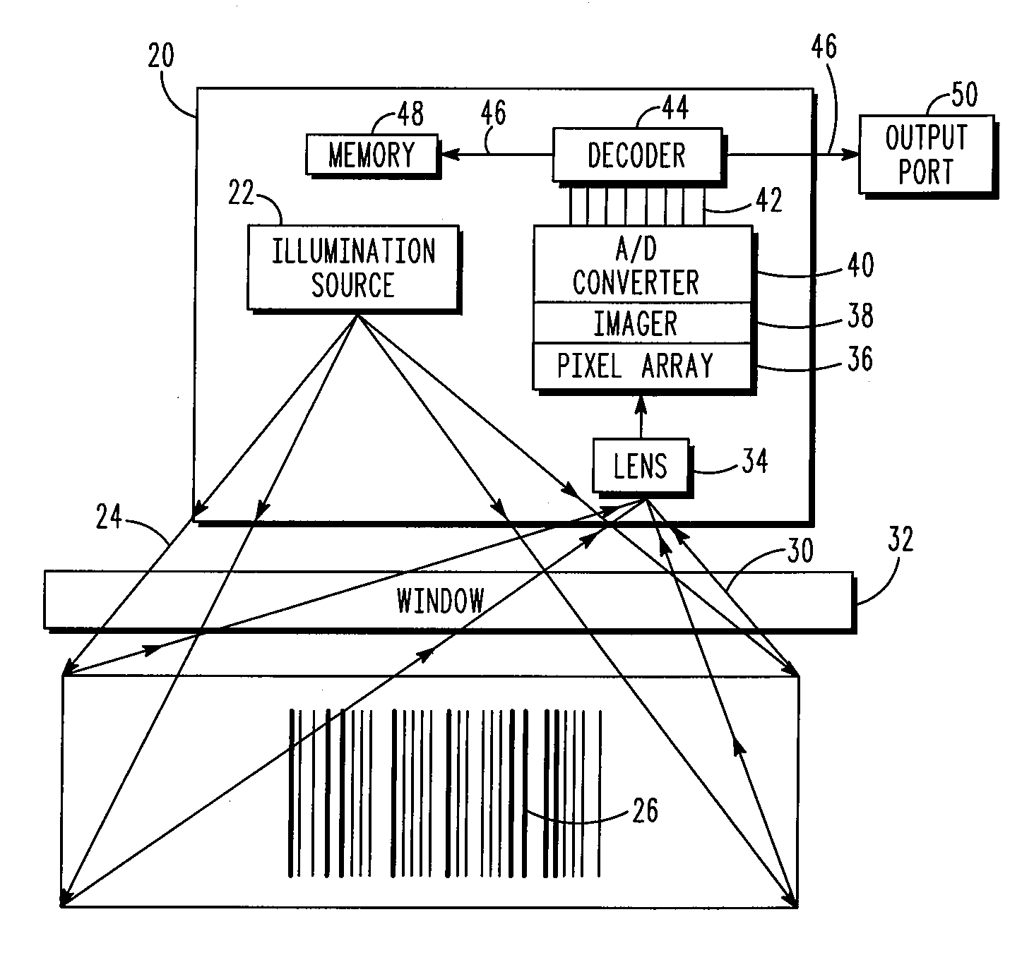
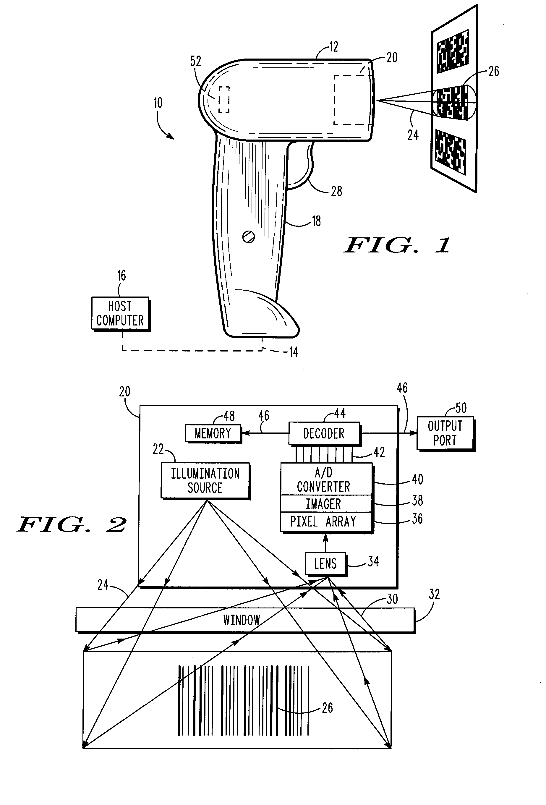
[0018]An imaging system 10 includes an imaging scanner 12 in communication 14 either through hard-wire or over-the-air (remote communication) to a host computer 16 as shown schematically in FIG. 1. The imaging scanner 12, in addition to imaging both 1D and 2D bar codes and postal codes, is also capable of capturing images and signatures. In one exemplary embodiment of the present invention, the imaging scanner 12 is a hand held portable imager supported in a housing 18 that can be carried and used by a user walking or riding through a store, warehouse, or plant for imaging bar codes for stocking and inventory control purposes.

[0019]However, it should be recognized that the imaging system 10 of the present invention, to be explained below, may be advantageously used in connection with any type of scanner or imaging device, be it portable or stationary. It is the intent of the present invention to encompass all such scanners and imagers.

[0020]Internal to the imaging scanner 12 is a sc...


PUM


Abstract

A method and apparatus for reducing the visual discomfort of the illumination generated by imaging scanners. The method includes (1) turning on a driving current for a illumination source during each of a series of exposure periods to provide illumination directed toward a target object; (2) capturing an image from the target object with photosensitive circuitry during at least one of the exposure periods; and (3) generating a pulse-width-modulation driving current that has a duty cycle changing with time between two consecutive exposure periods for making perceived gradual illumination changes between the two consecutive exposure periods. The duty cycle decreases from the value of 100% to a minimal value after each of the exposure periods and increases from the minimal value to the value of 100% before each of the exposure periods.

Description

FIELD OF THE DISCLOSURE[0001]The present disclosure relates generally to imaging scanners for reading optical indicia.BACKGROUND[0002]Various electro-optical systems have been developed for reading optical indicia, such as bar codes. A bar code is a coded pattern of graphical indicia comprised of a series of bars and spaces of varying widths, the bars and spaces having differing light reflecting characteristics. Some of the more popular bar code symbologies include: Uniform Product Code (UPC), typically used in retail stores sales; Code 39, primarily used in inventory tracking; and Postnet, which is used for encoding zip codes for U.S. mail. Systems that read and decode bar codes employing charged coupled device (CCD) or complementary metal oxide semiconductor (CMOS) based imaging systems are typically referred to hereinafter as imaging systems, imaging-based bar code readers, or imaging scanners.[0003]Imaging systems electro-optically transform the graphic indicia into electrical s...

Claims


Application Information

Patent Timeline
Patent Type & Authority Applications(United States)
IPC IPC(8): H04N5/335
CPCG06K7/10732
Inventor STRAT, ASKOLDBOEHM, THOMASLACKEMANN, TOMPANG, ROBERT
Owner SYMBOL TECH INC
Why Eureka
Try Eureka