Stereo-image registration and change detection system and method

a technology of image registration and change detection, applied in the field of remote sensing imagery systems, can solve problems such as method errors and hampered by the complexity of registering images of the same scanned area

Active Publication Date: 2010-12-02
ISRAEL AEROSPACE IND
View PDF6 Cites 69 Cited by
  • Summary
  • Abstract
  • Description
  • Claims
  • Application Information

AI Technical Summary

Benefits of technology

[0013]d) stereo-matching at least two images, each one being or derived from different one of said at least two groups and same or different sets, using

Problems solved by technology

In spite of the fact that known methods exist in the art for detecting differences or changes between images taken from the same or similar angle, these methods are error prone due to the high rate of false alarm (FA) change detections.
However, de

Method used


Image

  • Stereo-image registration and change detection system and method
  • Stereo-image registration and change detection system and method
  • Stereo-image registration and change detection system and method

Examples


Embodiment Construction

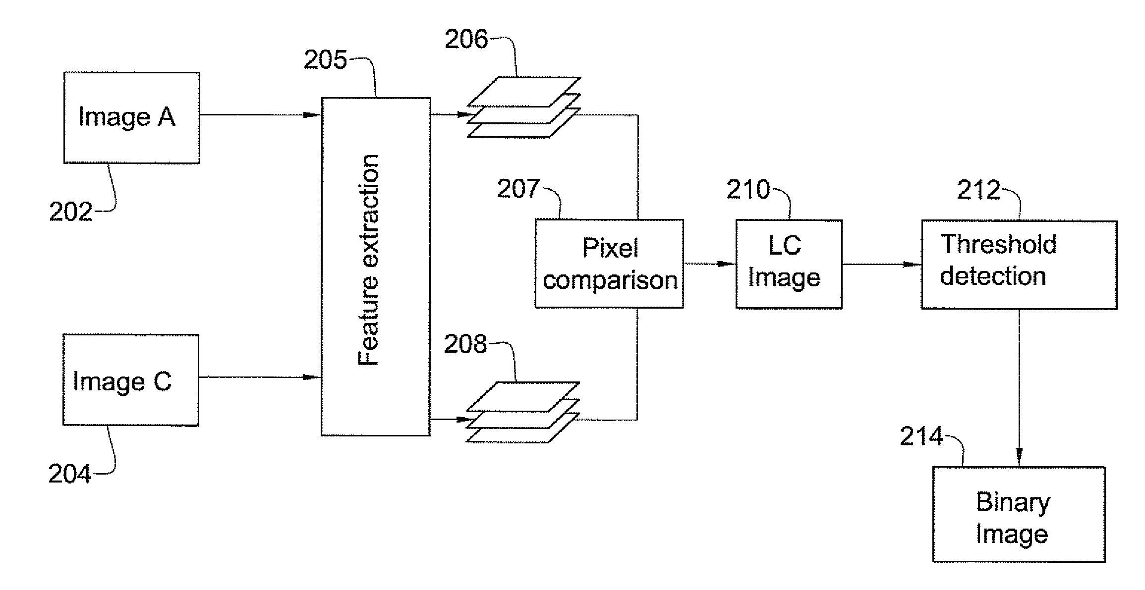
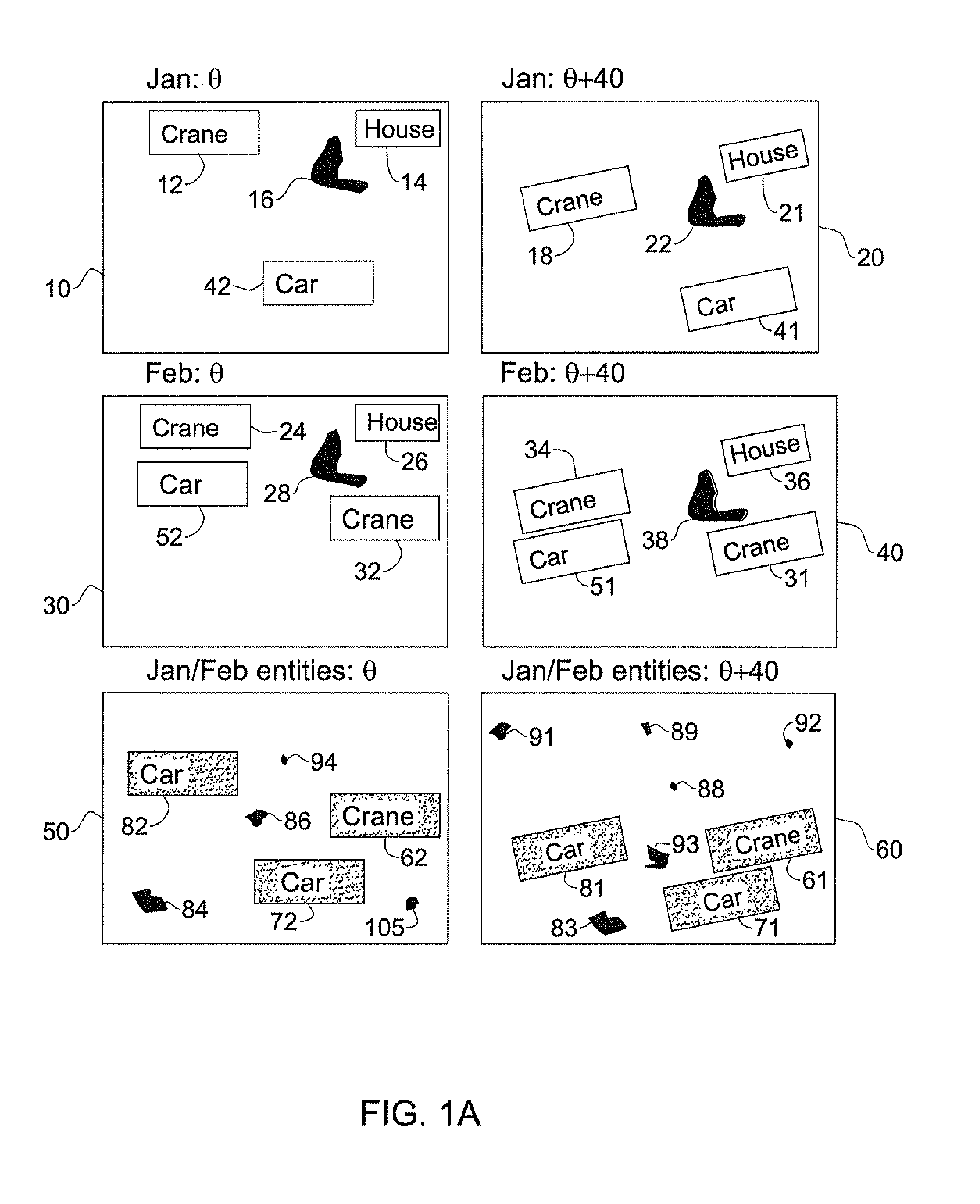
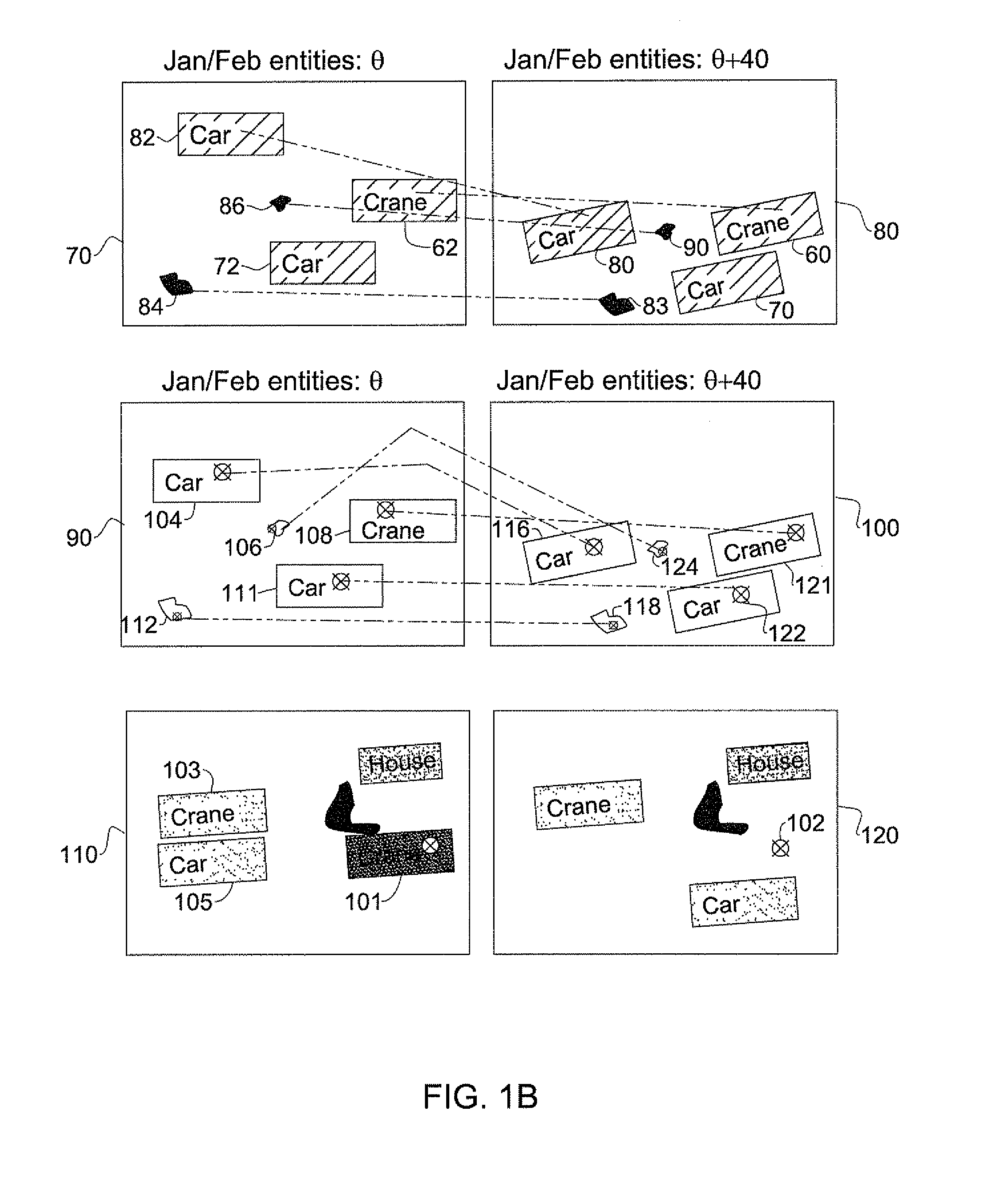
[0077]The principles and operation of a remote sensing imagery system and method according to the present invention may be better understood with reference to the drawings and accompanying description.

[0078]Before explaining at least one embodiment of the invention in detail, it is to be understood that the invention is not limited in its application to the details of construction and the arrangement of the components set forth in the following description or illustrated in the drawings. The invention is capable of other embodiments or of being practiced or carried out in various ways. Also, it is to be understood that the phraseology and terminology employed herein is for the purpose of description and should not be regarded as limiting. In accordance with certain embodiments of the present invention, the phraseology and terminology which involves the word “stereo” (such as “stereoscopic images”, “stereo matching” and the like) is numerically non-limiting and should be interpreted ...


PUM


Abstract

A system and method for registering stereoscopic images comprising: obtaining at least two sets of stereoscopic images, each one of the at least two sets including at least two images that are taken from different angles, determining at least two groups of images, each one of the groups including at least two images that are respective images of at least two of the sets or are derived therefrom. For each one of the groups, calculating a respective optimal entities list and stereo-matching at least two images, each one being or derived from different one of the at least two groups and same or different sets, using at least four optimal entities from each one of the optimal entities list, thereby giving rise to at least one pair of registered stereoscopic images.

Description

FIELD OF THE INVENTION[0001]The present invention relates generally to remote sensing imagery systems and more particularly to sensing imagery systems which utilize multiple images of a scene.BACKGROUND OF THE INVENTION[0002]Remote sensing imagery is used in diverse fields such as urban planning, military, intelligence and disaster monitoring. Many of the applications require the ability to detect changes between images taken at successive time points. In spite of the fact that known methods exist in the art for detecting differences or changes between images taken from the same or similar angle, these methods are error prone due to the high rate of false alarm (FA) change detections. False alarm detection is typically caused by two dimensional differences (such as shadow changes) between the images that do not actually reflect a true, physical, three dimensional (“volumetric”) difference such as a structure appearing in a location previously unoccupied, or a vehicle no longer appea...

Claims


Application Information

Patent Timeline
IPC IPC(8): G06K9/00
CPCG06T2207/10021G06T2207/30181G06T7/593G06T7/285
Inventor ABRAHAM, MICHAELGOSTYNSKI, VICTOR
Owner ISRAEL AEROSPACE IND
Why Eureka
Try Eureka