Energy storage system

a technology of energy storage and energy storage devices, applied in the direction of fluid couplings, electric generator control, couplings, etc., can solve the problems of less efficient plants, prone to overheating, and typically older peak plants

Inactive Publication Date: 2010-12-09
IVY STEVEN THOMAS +1
View PDF3 Cites 40 Cited by
  • Summary
  • Abstract
  • Description
  • Claims
  • Application Information

AI Technical Summary

Benefits of technology

[0017]An apparatus for making a large flexible bladder at the location where it will be used comprises two parallel twin-rail tracks wherein the two tracks are separated by a distance somewhat more than the width of the bladder to be constructed; a first and a second rail car with rail-wheels for engaging the twin-rail tracks, wherein the first rail car is disposed on one twin-rail track and the second rail car is disposed on the other parallel twin-rail track; a relatively tall superstructure mounted on each of the first and second rail cars; a gantry with two e

Problems solved by technology

However, when demand rises, these utilities may bring “peaking plants” online to meet the additi

Method used


Image

  • Energy storage system
  • Energy storage system
  • Energy storage system

Examples


Embodiment Construction

[0036]Although the preferred embodiments are described in detail, it should be understood that various changes, substitutions and alterations can be made therein without departing from the spirit and scope of the invention as defined by the appended claims.

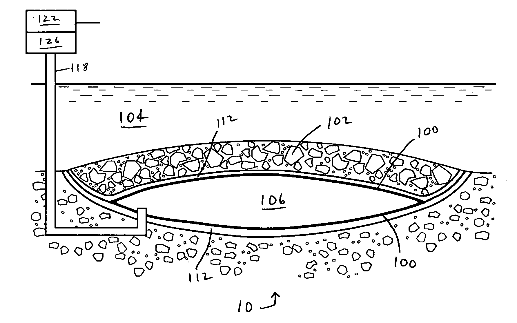
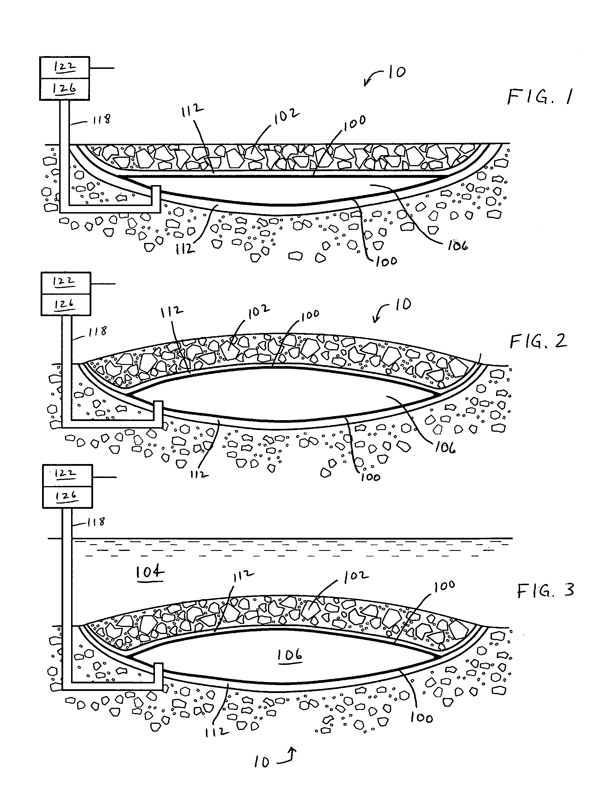
[0037]Referring to FIGS. 1-3, a system 10 for storing energy includes a buried flexible bladder 100 that may be used as used as an energy storage device. A layer of sand 112 may be disposed over the top and under the bottom of the bladder 100. This layer of sand 112 serves to cushion the bladder 100 to some extent and tends to protect the bladder 100 from being punctured by relatively sharp rocks that might be disposed in the surrounding strata. However, the layers of sand 112 are not critical to this invention and can be omitted.

[0038]In one embodiment, shown in FIGS. 1 and 2, bladder 100 is covered with a relatively thick overfill 102 of earth, stones, or any other material with substantial mass. In another embodiment, shown in ...


PUM


Abstract

Energy can be stored by directing fluid into an expandable receptacle that has a relatively heavy mass above it. The fluid fills the receptacle such that it expands and lifts up the heavy mass above it. At a time when energy is needed, the fluid can be allowed to flow out of the receptacle and through a turbine or hydraulic motor to generate power or electricity. Intermittent or unreliable sources of power can be used to fill the receptacle, or power from a power grid can be used to fill the receptacle at times that are off-peak. During peak-load times, the potential energy of the fluid in the receptacle can be converted to power. The receptacle can also be used to control water flows and can provide a source of power and potable water to a community.

Description

CROSS-REFERENCE TO RELATED APPLICATION[0001]The present application claims the benefit of 35 U.S.C. section 111(b) provisional patent application Ser. No. 61 / 184,515 filed on Jun. 5, 2009 and entitled “Energy Storage System Utilizing Underground Bladder”.STATEMENT REGARDING FEDERALLY SPONSORED RESEARCH OR DEVELOPMENT[0002]Not applicable.THE NAMES OF THE PARTIES TO A JOINT RESEARCH AGREEMENT[0003]Not applicable.INCORPORATION BY REFERENCE OF MATERIAL SUBMITTED ON A COMPACT DISC[0004]Not applicable.BACKGROUND OF THE INVENTION[0005]The following disclosure relates to energy storage devices and, in particular, underground storage devices wherein a pressurized fluid is utilized as a means of storing energy.[0006]In many instances, electric utilities operate large, efficient power generating plants to produce electricity at rate sufficient to meet a base load. However, when demand rises, these utilities may bring “peaking plants” online to meet the additional demand. Peaking plants are typ...

Claims


Application Information

Patent Timeline
IPC IPC(8): F15B1/027F15B1/08B65G5/00E02B3/00F03D9/02
CPCF03G3/00B65G5/00F15B1/024F15B1/027
Inventor IVY, STEVEN THOMASEASTWOOD, GUY CARL
Owner IVY STEVEN THOMAS
Why Eureka
Try Eureka