Apparatus for testing object strength

a technology for object strength and apparatus, applied in the direction of instruments, measurement devices, scientific instruments, etc., can solve the problems of relative weakness of seals, risk of rupture, and inability to bind corners well

Inactive Publication Date: 2010-12-09
HONG FU JIN PRECISION IND (SHENZHEN) CO LTD +1
View PDF2 Cites 10 Cited by
  • Summary
  • Abstract
  • Description
  • Claims
  • Application Information

AI Technical Summary

Problems solved by technology

As a result, the corners may not bind well, presenting relative weakness of the seal therebetween.
C

Method used


Image

  • Apparatus for testing object strength
  • Apparatus for testing object strength
  • Apparatus for testing object strength

Examples


Embodiment Construction

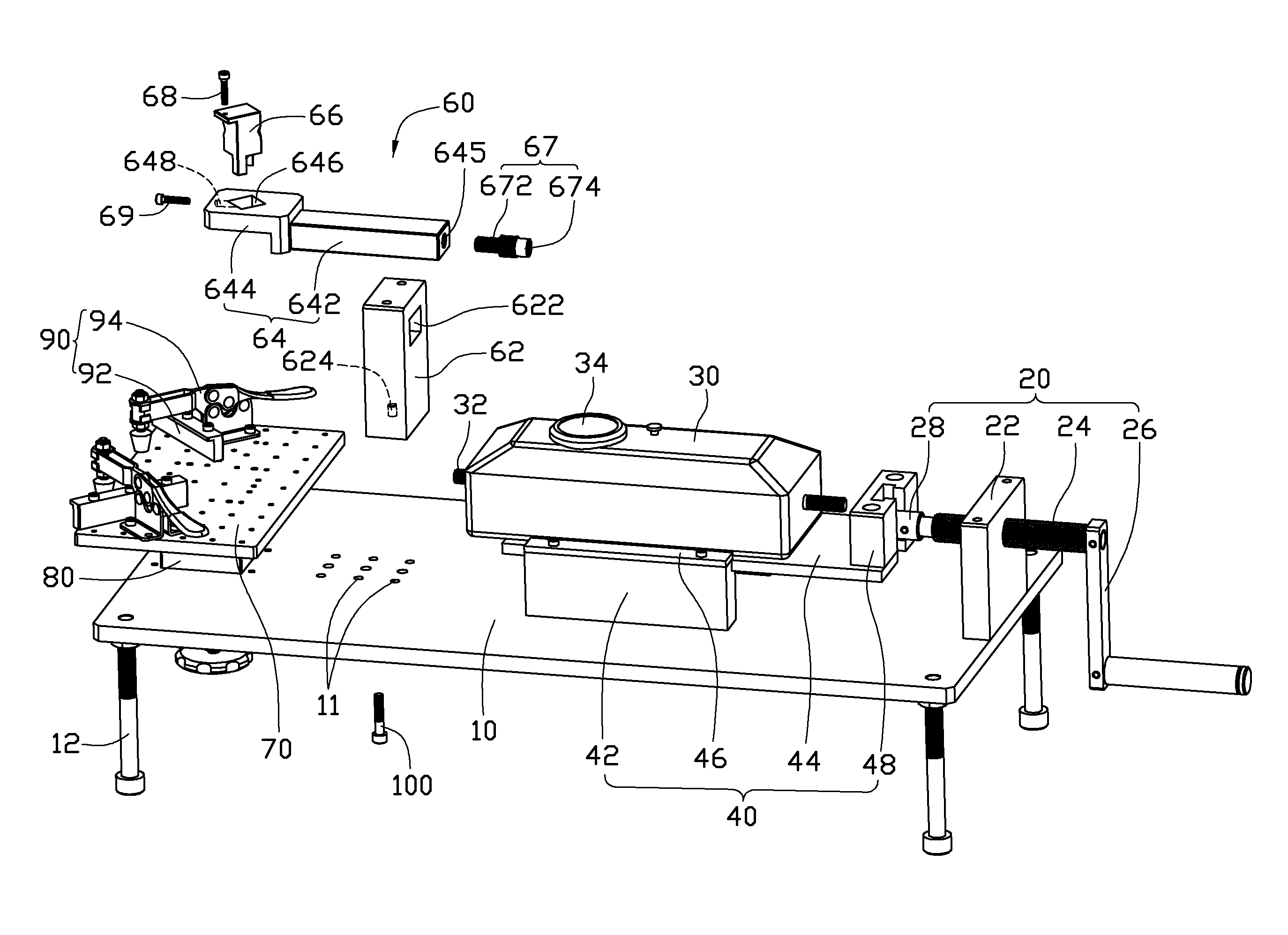
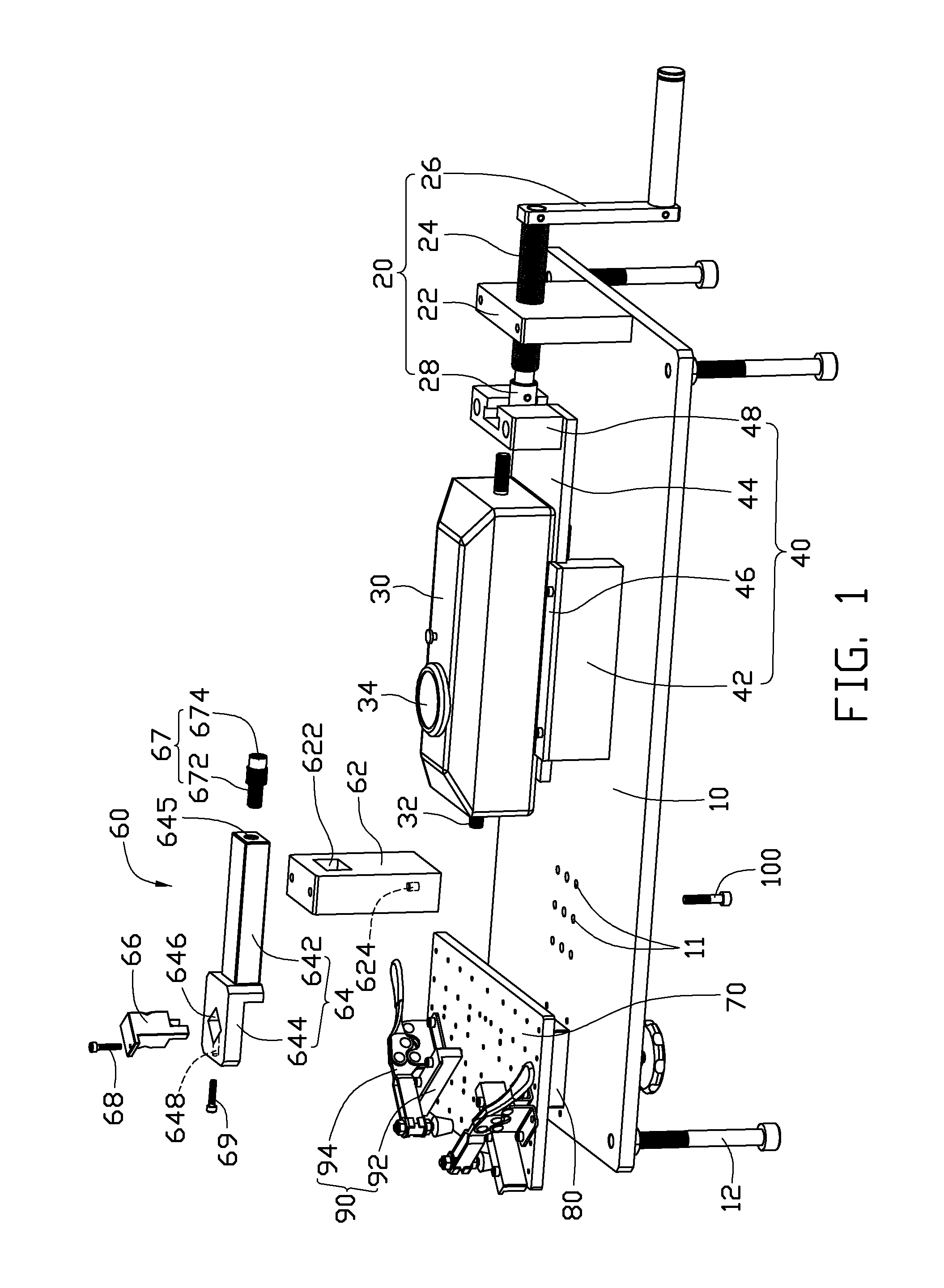
[0012]Referring to FIG. 1, a first exemplary embodiment of an apparatus for testing object strength includes a rectangular support platform 10, a plurality of support bolts 12 under the platform 10, an adjustment mechanism 80 installed on a first end of the platform 10, an installation board 70 fixed on the adjustment mechanism 80 for supporting the object, a clamping mechanism 90 which can be placed at different positions on the installation board 70, a drive mechanism 20 installed on a second end of the platform 10 opposite to the first end, a force gauge 30, an installation mechanism 40 positioned between the adjustment mechanism 80 and the drive mechanism 20 for installation of the force gauge 30 thereon, and a push-pull mechanism 60.

[0013]The platform 10 includes several sets of installation holes 11 defined therein and between the adjustment mechanism 80 and the installation mechanism 40.

[0014]The adjustment mechanism 80 is movable vertical to the platform 10 to adjust the ins...


PUM


Abstract

An apparatus for testing strength of a corner portion of an object includes a support platform, an installation mechanism having a slidable plate mounted on the platform, a force gauge fixed to the slidable plate, a drive mechanism connected to the slidable plate to move the slidable plate, and a push-pull mechanism. The push-pull mechanism is connected to the force gauge to be pushed or pulled by the force gauge and exerts push or pull force on the corner portion of the object.

Description

CROSS-REFERENCES TO RELATED APPLICATION[0001]A relevant subject matter is disclosed in the co-pending U.S. patent application Ser. No. 12 / 551,444 filed on Aug. 31, 2009, and entitled “APPARATUS FOR TESTING STRENGTH OF OBJECTS”, and a co-pending U.S. patent application entitled “APPARATUS FOR TESTING OBJECT STRENGTH” filed at the same date as this patent application, which are assigned to the same assignee as this patent application.BACKGROUND[0002]1. Technical Field[0003]The disclosure relates to apparatuses for testing object strength, and particularly, to an apparatus for testing strength of molded products.[0004]2. Description of Related Art[0005]Typically, corners of an injection molded product are formed by influx of two or more streams of molten material. As a result, the corners may not bind well, presenting relative weakness of the seal therebetween. Consequently, a risk of rupture is present.[0006]In practice, there is a need to test the strength of injection molded product...

Claims


Application Information

Patent Timeline
IPC IPC(8): G01N3/00
CPCG01N2203/0067G01N3/08
Inventor ZHANG, BING-JUN
Owner HONG FU JIN PRECISION IND (SHENZHEN) CO LTD
Why Eureka
Try Eureka