Universal shoe box

a shoe box and universal technology, applied in the field of shoe boxes, can solve the problems of impaling the stackability and support of the shoe box placed thereon, and achieve the effects of avoiding the dropping or misplacing of the top of the shoe box, convenient and efficient identification of the shoe, and more reliable suppor

Inactive Publication Date: 2010-12-16
GOODMAN WILBERT BLAIR
View PDF23 Cites 42 Cited by
  • Summary
  • Abstract
  • Description
  • Claims
  • Application Information

AI Technical Summary

Benefits of technology

[0020]These features of the shoe box uniquely enable the mounting of one shoe box on top of another in a stackable configuration. These features further allow one shoe box to be precisely positioned on top of another shoe box, with the insertion of the tabs on the lower shoe box into the recesses located on the upper shoe box such that the upper shoe box will not be dislodged or slip off the lower shoe box. In this embodiment, the shoe box is able to support the second shoe box above it, the second shoe box is able to support the third shoe box above it and so forth, without risk of slippage or dislodgment of one or more shoe boxes from the stacked configuration. As such, the space-saving features of this stackable configuration may be maintained. Furthermore, the absence of a removable lid avoids the dropping or misplacing of the top of the shoe box. This embodiment of the shoe box may be most advantageously used in the aftermarket residential setting by an individual desiring to store a pluarility of shoe boxes in a stackable configuration in their closet. In particular, the pivoting mechanism enables the front face to be extended in an open position, thereby enabling removal of a pair of shoes from an individual shoe box, while still maintaining the stackable configuration of all shoe boxes stored on top of the shoe box.
[0021]In a further embodiment of the present invention, the non-removable top face of the shoe box may be hingedly attached to the rear face of the shoe box. In another embodiment, the non-removable top face may be hingedly attached to the first face of the shoe box. In yet a further embodiment, the non-removable top face may be hingedly attached to the second face of the shoe box. As discussed above, these embodiments uniquely enable the shoe box to be maintained either individually or in a stackable configuration without risk of dislodgment of a lid that is commonly found in many prior art shoe boxes. Accordingly, the non-removable top face may provide more reliable support, especially in a stackable configuration.
[0022]In another embodiment, the shoe box may further include a shoe label on the front face ident

Problems solved by technology

US2006/0054674 A1 as discussed above has a removable lid that may be dislodged

Method used


Image

  • Universal shoe box
  • Universal shoe box
  • Universal shoe box

Examples


Embodiment Construction

[0034]The drawings referred to herein are for the purposes of illustrating the preferred embodiments of the present invention and not for the purposes of limiting the same.

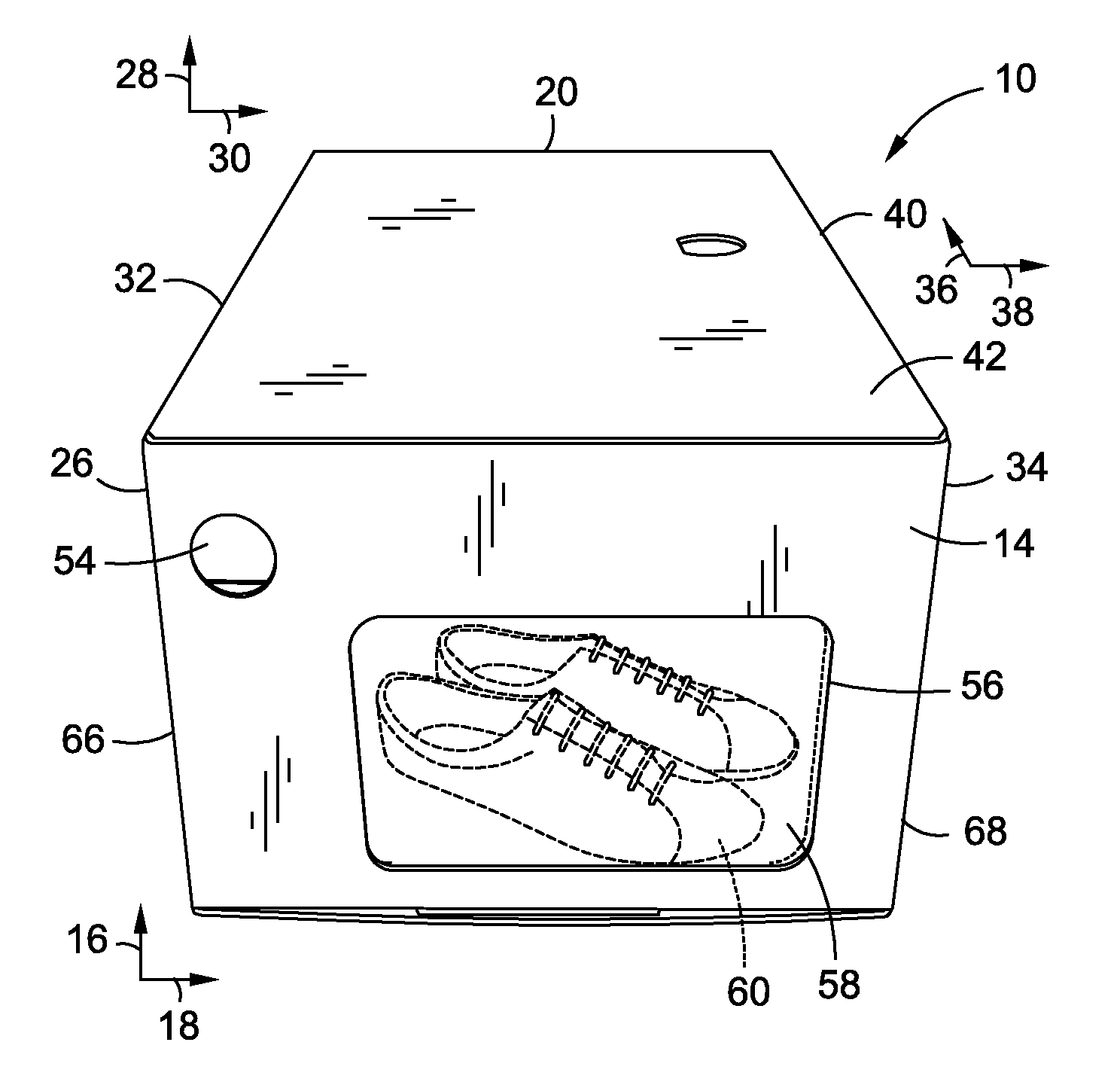
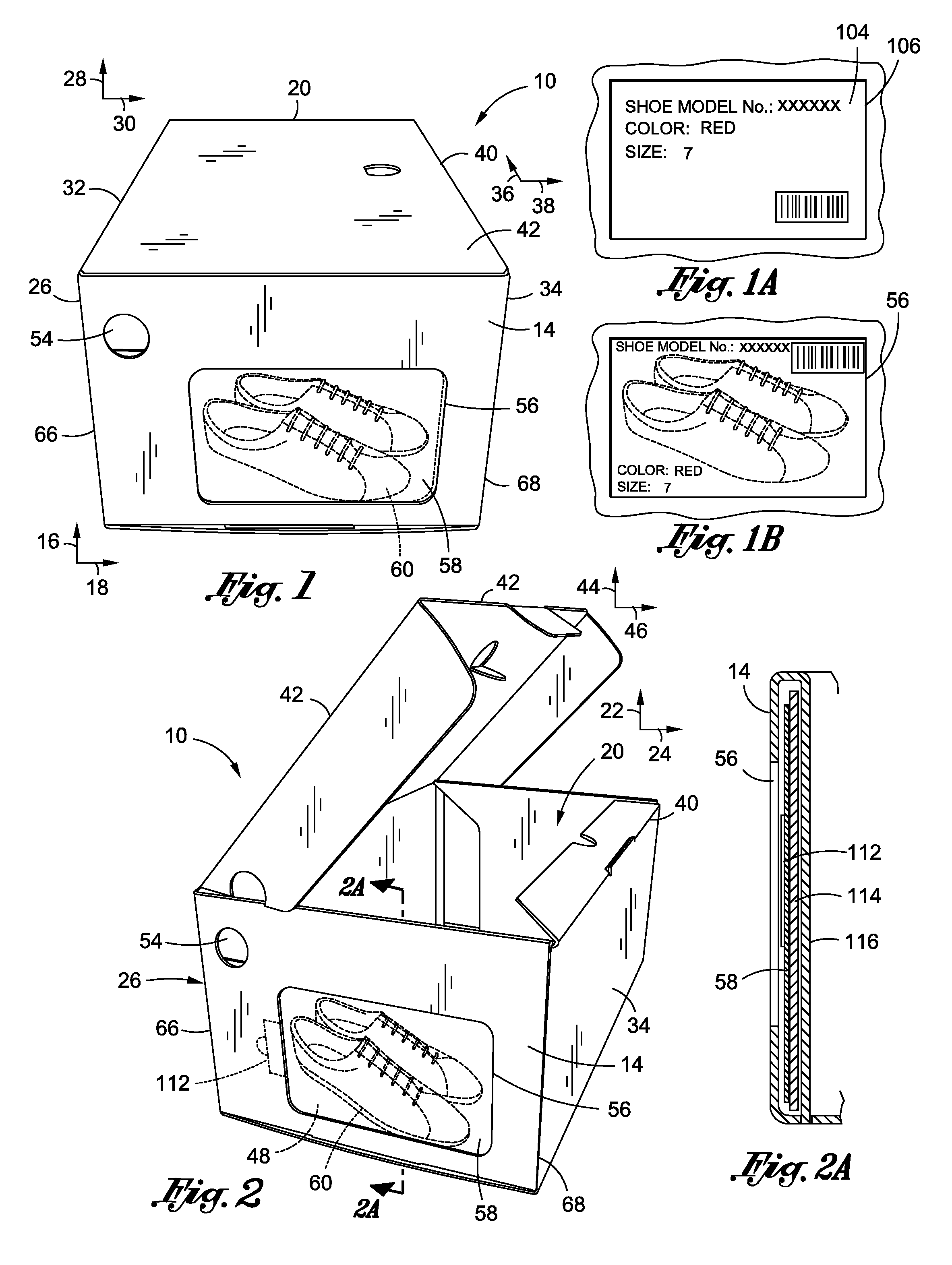
[0035]FIG. 1 is an embodiment of the universal shoe box 10. A non-removable top face 42 and a front face 14 are visible. The top face 42 is “non-removable” in that it is hingedly attached to at least one adjacent face. Although the top face 42 depicted in FIG. 1 is hingedly attached to the first face 26, it is also contemplated within the scope of the present invention that various embodiments of the shoe box 10 may have the top face 42 hingedly-attached to either the rear face 20, the front face 14, or the second face 34. The perspective shown in FIG. 2 visibly depicts the rear face 20 and the second face 34 of the shoe box 10.

[0036]Still referring to FIG. 1, the front face 14 is generally defined by a longitudinal front face axis 16 and a lateral front face axis 18. The first face 26 and the second face 34 are g...


PUM


Abstract

A universal shoe box has plural faces formed of a common continuous material with each face having a preferential fold disposed between adjacent faces which enable the quick assembly and disassembly of the shoe box. The shoe box includes a display window to enable quick and efficient visual identification of the contents of the shoe box on an image/photograph depicted on a card which may be disposed within the window. Two embodiments of the shoe box are presented, one primarily suited for residential/after market usage and one primary suitable for retail storage usage.

Description

CROSS-REFERENCE TO RELATED APPLICATIONS[0001]Not ApplicableSTATEMENT RE: FEDERALLY SPONSORED RESEARCH / DEVELOPMENT[0002]Not ApplicableBACKGROUND[0003]The present invention relates generally to a universal shoe box.[0004]When a customer in a shoe store requests a pair of shoes to try on, a sales person typically goes to a room filled with shoe inventory stored in boxes that may identify a particular shoe by style no., model no., size, color, and / or other information describing the contents of the box. Often, the numbers and / or letters printed on a box to describe its contents are small and difficult to read. As a result, the sales person looking for a pair of shoes requested by a customer may end up spending an inordinate amount of time looking for the specific box that contains the requested shoes. Needless to say, this reduces the amount of time the sales person may spend with the customer, thereby affecting the customer's perception of the quality of customer service, as well as po...

Claims


Application Information

Patent Timeline
IPC IPC(8): B65D85/18B65D25/54
CPCB65D5/0015B65D5/22B65D5/4237B65D5/6685B65D5/721
Inventor GOODMAN, WILBERT BLAIR
Owner GOODMAN WILBERT BLAIR
Why Eureka
Try Eureka