Vehicle Brake System Having A Pump

a technology of brake system and pump, which is applied in the field of vehicle brake system, can solve the problems of unwanted noise, unwanted noise, and sudden filling of the prechamber, and achieve the effects of preventing the generation of noise or dropping of the brake pedal, avoiding customer complaints, and improving travel comfor

Inactive Publication Date: 2008-08-21
ROBERT BOSCH GMBH
View PDF2 Cites 3 Cited by
  • Summary
  • Abstract
  • Description
  • Claims
  • Application Information

AI Technical Summary

Benefits of technology

[0005]It an object of the invention to create a vehicle brake system of the type defined at the outset in which the aforementioned side effects of sudden filling of the prechamber of the pump are avoided.
[0006]The object is attained according to the invention, with a vehicle brake system of the generic type in question, in which a bypass valve is connected parallel to the valve that leads to the prechamber, and the bypass valve is switched as a function of the pressure difference between the ambient pressure and the prechamber pressure. The bypass valve of the invention makes it possible to avoid an excessively great, sudden pressure equalization via the valve leading to the prechamber in the vehicle brake system, and thus completely prevents the generation of noise or dropping of the brake pedal. The travel comfort can thus be improved, and customer complaints can be avoided.
[0007]In an advantageous refinement of the vehicle brake system of the invention, excessive evacuation of the prechamber of the pump is prevented in particular by providing a control unit which opens the bypass valve if the prechamber pressure drops below ambient pressure and closes it again if the prechamber pressure rises to or above the ambient pressure. With the control unit of this kind and the associated bypass valve, according to the invention the pressure in the prechamber of the pump of the vehicle brake system is accordingly always kept at at least the ambient pressure level.
[0009]The control unit can moreover be designed overall without expensive sensors and actuating means by providing that the bypass valve, actuated by a simple adjuster, is furthermore closed hydraulically by the prechamber pressure. This adjuster as well can be designed as purely mechanical.
[0011]The bypass valve of the invention and the thus-attained avoidance of excessive pressure equalization events in vehicle brake systems is especially advantageous in conjunction with high-pressure switching valves in hydraulic brake systems.

Problems solved by technology

In certain operating states of the vehicle brake system, this low pressure can become so great that in the event the valve later opens, sudden filling of the evacuated prechamber can ensue.
This filling action can cause an undesirable loud noise, hammering within the pressure flow, and / or dropping of the associated brake pedal.
All these side effects are unwanted.
Such an evacuation necessarily occurs often, however, because the fill level in the reservoir can only be estimated via a hydraulic model, yet on the other hand it must be assured that the reservoir is completely evacuated at certain times.

Method used


Image

  • Vehicle Brake System Having A Pump
  • Vehicle Brake System Having A Pump
  • Vehicle Brake System Having A Pump

Examples


Embodiment Construction

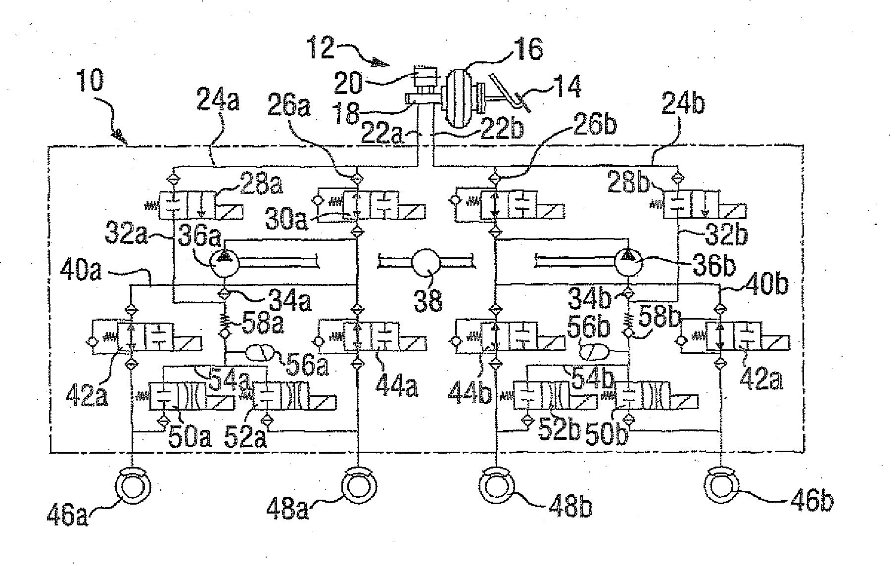
[0017]In FIG. 1, the hydraulic circuit diagram of a vehicle brake system 10 in accordance with the prior art is shown. The vehicle brake system 10 contains a brake actuation unit 12, which in the conventional way includes a brake pedal 14, a brake booster 16, a master cylinder 18, and a brake fluid reservoir 20.

[0018]Two lines 22a and 22b, each belonging to one of two separate brake circuits, are connected to the master cylinder 18 and to the brake fluid reservoir 20 located there. These two brake circuits are constructed substantially identically and are hereinafter distinguished by the use of the reference letters “a” and “b”. For the sake of simplification, the following description will be limited to the first of these two brake circuits, and it is assumed that the other brake circuit, as noted, is structurally essentially identical.

[0019]The line 22a splits into two lines 24a and 26a, to which a high-pressure switching valve 28a and a low-pressure switching valve 30a, respectiv...


PUM


Abstract

Disclosed is a vehicle brake system having a pump and a prechamber, from which the pump can extract a fluid by suction, and having a switching valve, by means of which fluid can optionally be fed to the prechamber. A bypass valve connected in parallel with the switching valve is switched as a function of the pressure difference between the ambient pressure and the prechamber pressure.

Description

PRIOR ART[0001]The invention relates to a vehicle brake system having a pump and a prechamber from which the pump can aspirate a fluid, and having, a valve, by means of which fluid can be directed selectively to the prechamber.[0002]In the field of vehicle brake systems, the most various systems are known, in which a pump is provided for active reduction or buildup of brake pressure. From a prechamber, the pump aspirates brake fluid and pumps it then selectively back to a tank to reduce brake pressure (anti-lock mode of the vehicle brake system), or (for instance in an electronic stability program) the pump pumps hydraulic fluid in the direction of the vehicle brakes.[0003]In addition, within the hydraulic circuit into which the pump with its prechambers incorporated, a valve is also provided by means of which fluid can be selectively directed to the prechamber. In the known vehicle brake systems, when the valve is closed, low pressure can fundamentally be generated in the pump prec...

Claims


Application Information

Patent Timeline
Patent Type & Authority Applications(United States)
IPC IPC(8): B60T8/00
CPCB60T8/4872
Inventor BODMANN, CARSTEN
Owner ROBERT BOSCH GMBH
Why Eureka
Try Eureka