
Backlight system

a backlight system and control technology, applied in the field of backlight systems, can solve the problems of progressive degradation of the performance of the backlight, excessive waste of precious energy, and large spread of the luminous intensities of the light sources comprised in the backligh

Inactive Publication Date: 2010-12-16
KONINKLIJKE PHILIPS ELECTRONICS NV
View PDF8 Cites 7 Cited by
  • Summary
  • Abstract
  • Description
  • Claims
  • Application Information

AI Technical Summary

Benefits of technology

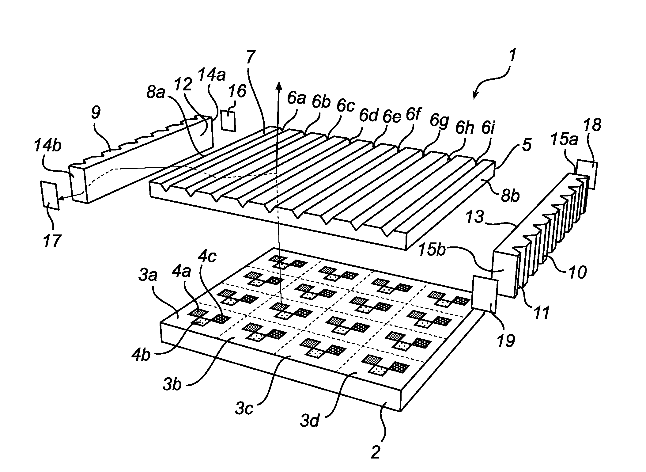
[0011]According to the present invention, these and other objects are achieved through an adaptively controllable backlight system, comprising a plurality of individually controllable light-sources arranged on a backlight panel to emit light in a direction substantially normal to the backlight panel; an outcoupling plate arranged adjacent to the backlight panel, and adapted to capture a fraction of the light emitted by the light-sources and to outcouple the fraction of light through at least one end-surface of the outcoupling plate; at least one light-guide arranged to receive the outcoupled light and adapted to guide the outcoupled light towards at least one end-surface of the light-guide; and at least one sensor arranged to receive the guided outcoupled light and adapted to provide a signal indicative of at least one property of the outcoupled light, thereby enabling adaptive control of the backlight system.
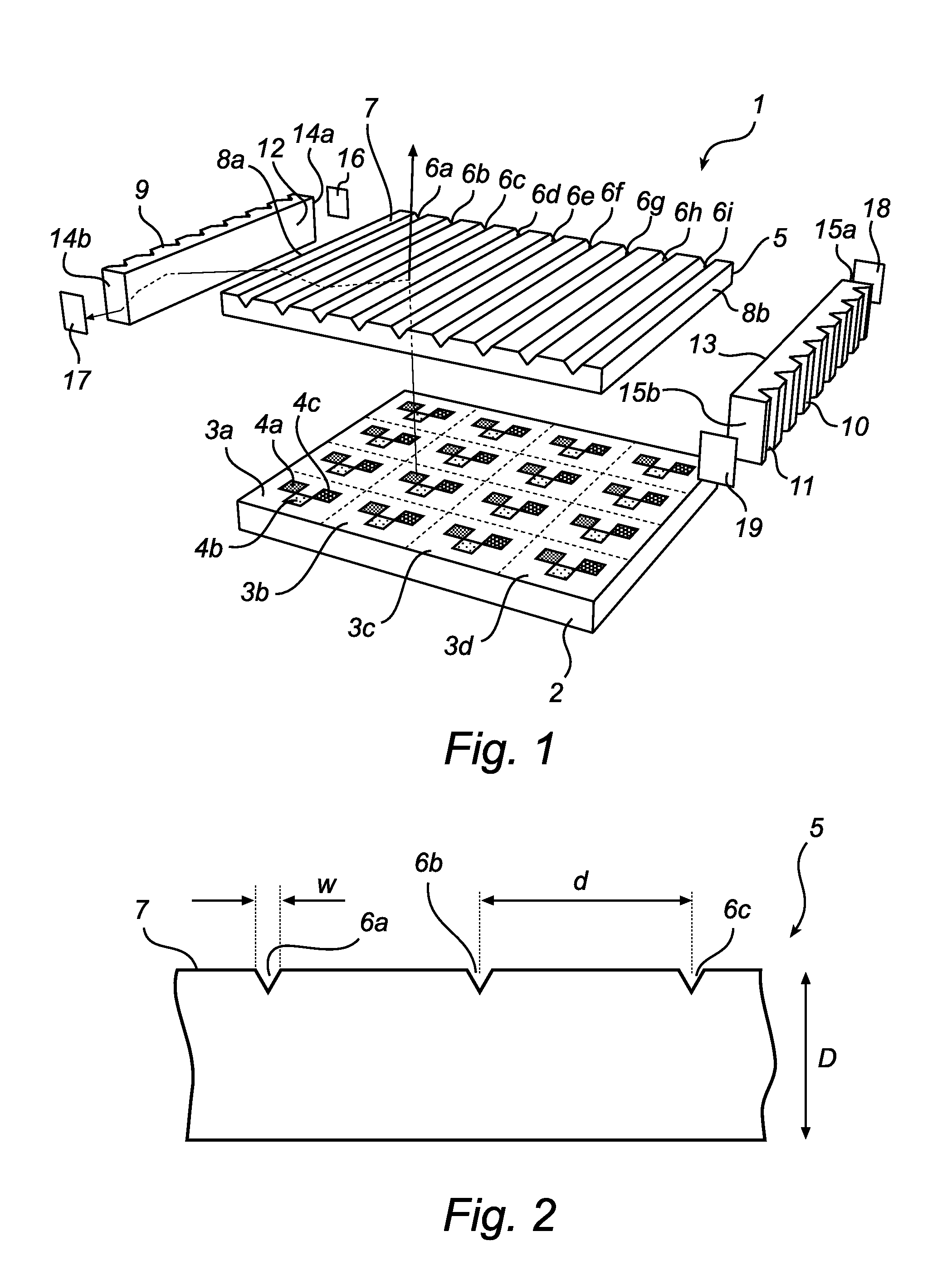
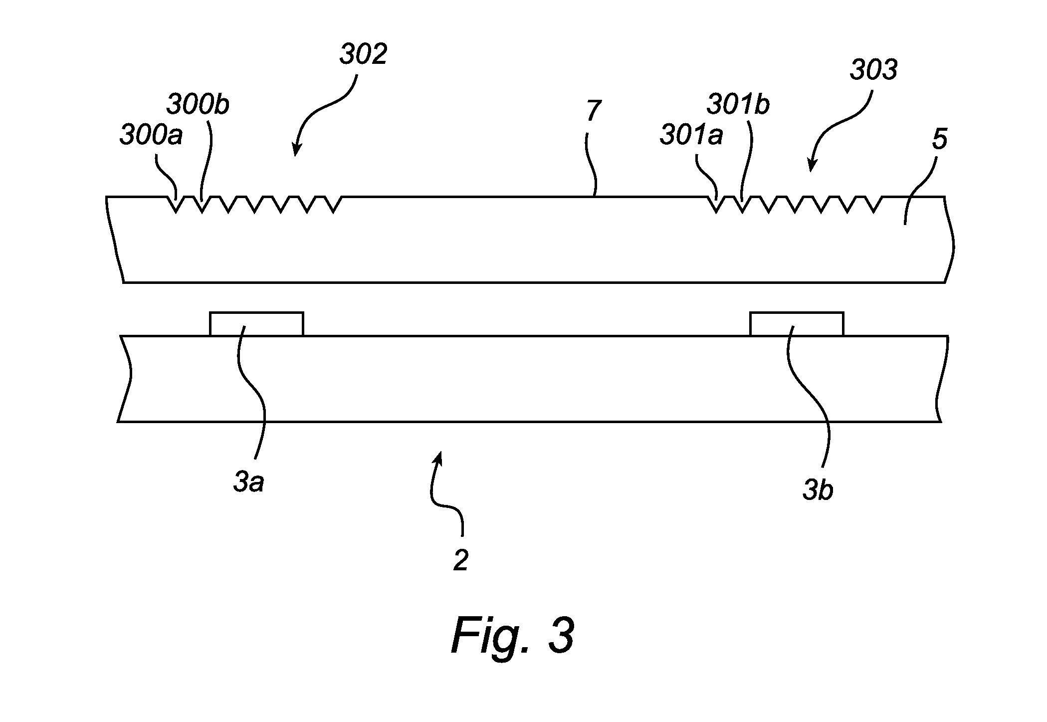
[0047]For example by providing a suitable structure configuration on the outcoupling plate, an increased uniformity of the light transmitted through the outcoupling plate may be achieved while, at the same time, capturing and outcoupling through the at least one outcoupling surface a suitably small fraction of the light emitted by the light-sources.

Problems solved by technology

While some kinds of flat panel displays, such as so-called plasma displays, are comprised of arrays of light emitting pixels, the majority of flat-panel displays have arrays of pixels, which can be switched between states but are unable to independently emit light.
When, however, as is often the case, only a very small proportion of the pixels are bright (in their trans-missive state), a correspondingly large fraction of the light emitted by the backlight is prevented from reaching the viewer and precious energy thus wasted.
However, the light-sources comprised in the backlight may exhibit a substantial spread of their luminous intensities at the same operating conditions.
Furthermore, aging of the light-sources may result in a progressive degradation of the performance of the backlight and, consequently, the display device comprising the backlight.
Consequently, individual variations among the emitting LEDs cannot be monitored and, accordingly, not compensated for.

Method used


Image

  • Backlight system
  • Backlight system
  • Backlight system

Examples


first embodiment

[0060]In FIG. 1, an exploded perspective view of the backlight system according to the present invention is schematically shown.

[0061]With reference to FIG. 1, the backlight system 1 has a backlight panel 2, which supports a plurality of individually controllable light-sources, here in the form of RGB-clusters 3a-d each including at least one of each of red, green and blue LEDs 4a-c. For the sake of clarity of drawing, only a few of the depicted RGB-clusters and RBG-LEDs are indicated by reference numerals. The backlight panel 2 is preferably provided in the form of a printed circuit board (PCB), or the like, having conductive traces connecting the light-sources 3a-d to a power supply (not shown), preferably via control circuitry (not shown) for enabling individual control of the individually controllable light-sources 3a-d. Although not indicated in FIG. 1, the RBG-clusters 3a-d may include a larger number of RGB-sub clusters, which are controllable as a group. The LEDs 4a-c is pre...

second embodiment

[0066]In FIG. 3, which is a section view of a portion of the backlight system according to the present invention, two adjacent light-sources 3a-b are provided on the backlight panel 2. On the top surface 7 of the outcoupling plate 5, outcoupling structures 300a-b and 301a-b are provided (for clarity of drawing, only two of the structures in each group of outcoupling structures are indicated by reference numerals). The outcoupling structures 300a-b and 301a-b are provided in groups 302 and 303 which are centered above each of the light-sources 3a and 3b, respectively. Between the two groups 302 and 303, no outcoupling structures are provided. Through the outcoupling plate configuration according to FIG. 3, the normal operation of the backlight system is disturbed as little as possible while still capturing and outcoupling a sufficiently large fraction of the emitted light to be able to measure the individual output of each of the light-sources 3a-b. Although no outcoupling structures...


PUM


Abstract

An adaptively controllable backlight system (1), having a plurality of individually controllable light-sources (3a-d) arranged on a backlight panel (2) to emit light in a direction substantially normal to the backlight panel (2). The backlight system (1) further comprises an outcoupling plate (5) arranged adjacent to the backlight panel (2), and adapted to capture a fraction of the light emitted by the light-sources (3a-d) and to outcouple the fraction of light through at least one outcoupling-surface (8a-b) of the outcoupling plate (5), and at least one light-guide (9, 10) arranged to receive the outcoupled light and adapted to guide the outcoupled light towards at least one outcoupling-surface (14a-b, 15a-b) of the light-guide (9, 10). Additionally, at least one sensor (16-19) is arranged to receive the guided outcoupled light and adapted to provide a signal indicative of at least one property of the outcoupled light, thereby enabling adaptive control of the backlight system (1).

Description

TECHNICAL FIELD[0001]The present invention relates to an adaptively controllable backlight system, and a display device comprising such a backlight system.TECHNICAL BACKGROUND[0002]Today, various types of flat-panel displays are used in a wide variety of applications, from mobile phone displays to large screen television sets. While some kinds of flat panel displays, such as so-called plasma displays, are comprised of arrays of light emitting pixels, the majority of flat-panel displays have arrays of pixels, which can be switched between states but are unable to independently emit light. Such flat-panel displays include the ubiquitously found LCD-displays. In order for such flat-panel displays to be able to display an image to a user, the pixel array must be illuminated by either a so-called backlight, in the case of a trans-missive type pixel array, or, in the case of a reflective type pixel array, by ambient light or a so-called front-light.[0003]A conventional backlight is compri...

Claims


Application Information

Patent Timeline
IPC IPC(8): G09G3/36
CPCG02B6/0016G02B6/0018G02B6/0068G02F1/133603G09G3/3426G09G2320/0626G09G2360/145G02F1/1335G02B6/0001
Inventor CENNINI, GIOVANNIPIJLMAN, FETZECORNELISSEN, HUGO JOHAN
Owner KONINKLIJKE PHILIPS ELECTRONICS NV
Learn More