Depolarised WDM source

a wdm source and depolarised technology, applied in the direction of fiber transmission, transmission, distortion/dispersion elimination, etc., can solve the problems of limiting the efficacy of wdm signal in transmitting data from transmitter to receiver, affecting the effect of wdm signal in transmitting data, and becoming more significant, so as to achieve effective depolarisation and minimise the net pdg of the link

Inactive Publication Date: 2010-12-23
NEPTUNE SUBSEA IP LTD
View PDF4 Cites 13 Cited by
  • Summary
  • Abstract
  • Description
  • Claims
  • Application Information

AI Technical Summary

Benefits of technology

The present invention relates to an optical communication system which uses several groups of loading channels with different properties such as power and wavelength to achieve better performance. These groups help reduce interference between channels caused by polarization modes dispersion (PMD). By adjusting these parameters, we can control the output polarization and minimize the impact of PMD, resulting in improved quality of signals transmitted through the network.

Problems solved by technology

This patent discusses technical problem related to improving the performance of optical communication networks, particularly those utilizing Wavelength Division Multiplexing (WDM) technology. Non-linear effects caused by interactions between neighboring optical signals can create interference among them, reducing network efficiency. Additionally, the use of low-powered laser combs or poorly designed filtering techniques for launching loading channels can negatively impact data channel performance. Another challenge presented is polarization dependent gain (PDG), resulting from the alignment of optical signals in relation to nearby loading channels. PDG causes variations in channel power over time, potentially affecting both the OSNR and BER performance.

Method used


Image

  • Depolarised WDM source
  • Depolarised WDM source
  • Depolarised WDM source

Examples


Embodiment Construction

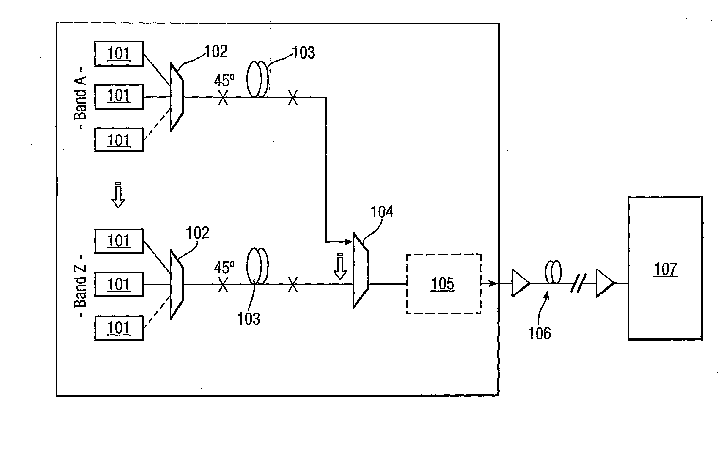
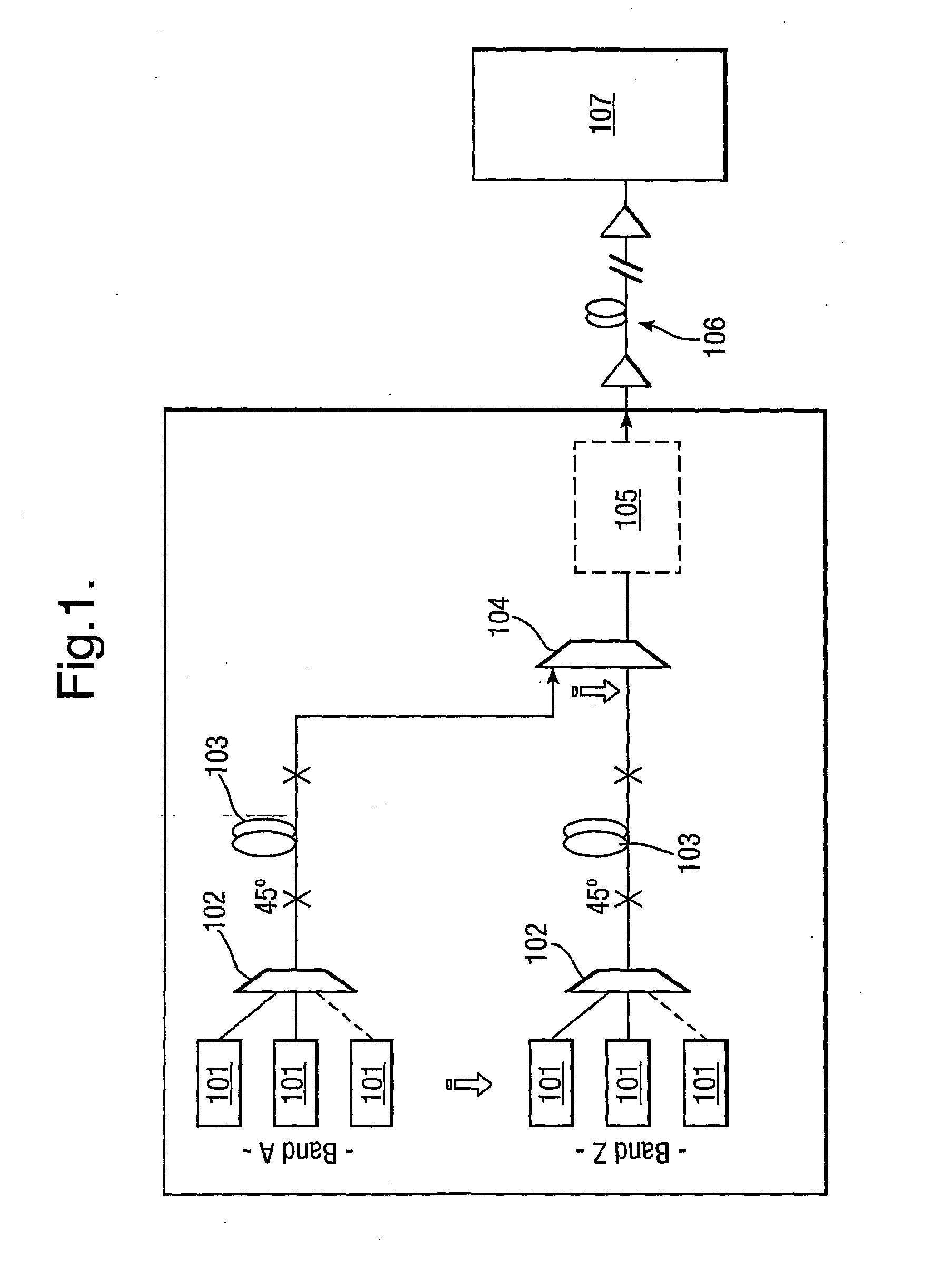
[0037]FIG. 1 shows a typical example of a Submarine Line Terminal Equipment (SLTE) transmission system. The channels may be any combination of loading and data channels. In the example shown, there are separate “bands” each comprising a plurality of channels. A WDM signal is formed of each band before the bands are multiplexed together to form the final signal.

[0038]As shown, a plurality of channel sources 101 in each band provide parallel polarised optical source signals that are multiplexed together by a polarisation maintaining multiplexor 102, thereby providing a polarised WDM signal. This polarised signal then passes through a DGD element 103 in order that the WDM signal may be depolarised, while the time-averaged DOP of each channel within the WDM signal remains substantial.

[0039]The depolarised WDM signals from each band are then combined by a further multiplexor 104. The combined signal passes through various other aggregate equipment 105 before being launched across a trans...


PUM


Abstract

A device and method for depolarising the total field of a wavelength division multiplexed (WDM) signal is provided. A polarisation maintaining multiplexor combines a plurality of optical signals to form a polarised multiplexed signal. The multiplexed signal is then passed through a differential group delay (DGD) element adapted to modify the polarisation state of one or more optical source signals within the multiplexed signal and thereby to at least partially depolarise the multiplexed signal.

Description


Claims


Application Information

Patent Timeline
Owner NEPTUNE SUBSEA IP LTD
Why Eureka
Try Eureka