Readily Removable Pump Crosshead

a crosshead and pump technology, applied in the direction of machines/engines, mechanical equipment, liquid fuel engines, etc., can solve the problems of time-consuming and frequent replacement of bushings

Inactive Publication Date: 2010-12-23
WEIR SPM
View PDF9 Cites 101 Cited by
  • Summary
  • Abstract
  • Description
  • Claims
  • Application Information

AI Technical Summary

Benefits of technology

[0008]The second crosshead member may have a neck protruding from the forward end of the second crosshead member. If so, the pony rod has a cavity that slides over the neck. Preferably, the retainer for joining the connecting rod to the first crosshead member comprises a wrist pin that inserts through a hole in the forward end of the connecting rod. The wrist pin is secured to the first crosshead member, such as by threaded fasteners. In the preferred embodiment, he first crosshead member has an enclosure wall surrounding the second crosshead member and a transverse wall extending transversely across the enclosure wall. The wrist pin fasteners extend through the transverse wall into the wrist pin. The enclosure wall of the first crosshead member may have holes adjacent opposite ends of the wrist pin for removing the wrist pin from the forward end of the connecting rod.

Problems solved by technology

Because of the high pressures and high stroke rate, operators must change the bushings frequently.
This procedure is time consuming.

Method used


Image

  • Readily Removable Pump Crosshead
  • Readily Removable Pump Crosshead
  • Readily Removable Pump Crosshead

Examples


Embodiment Construction

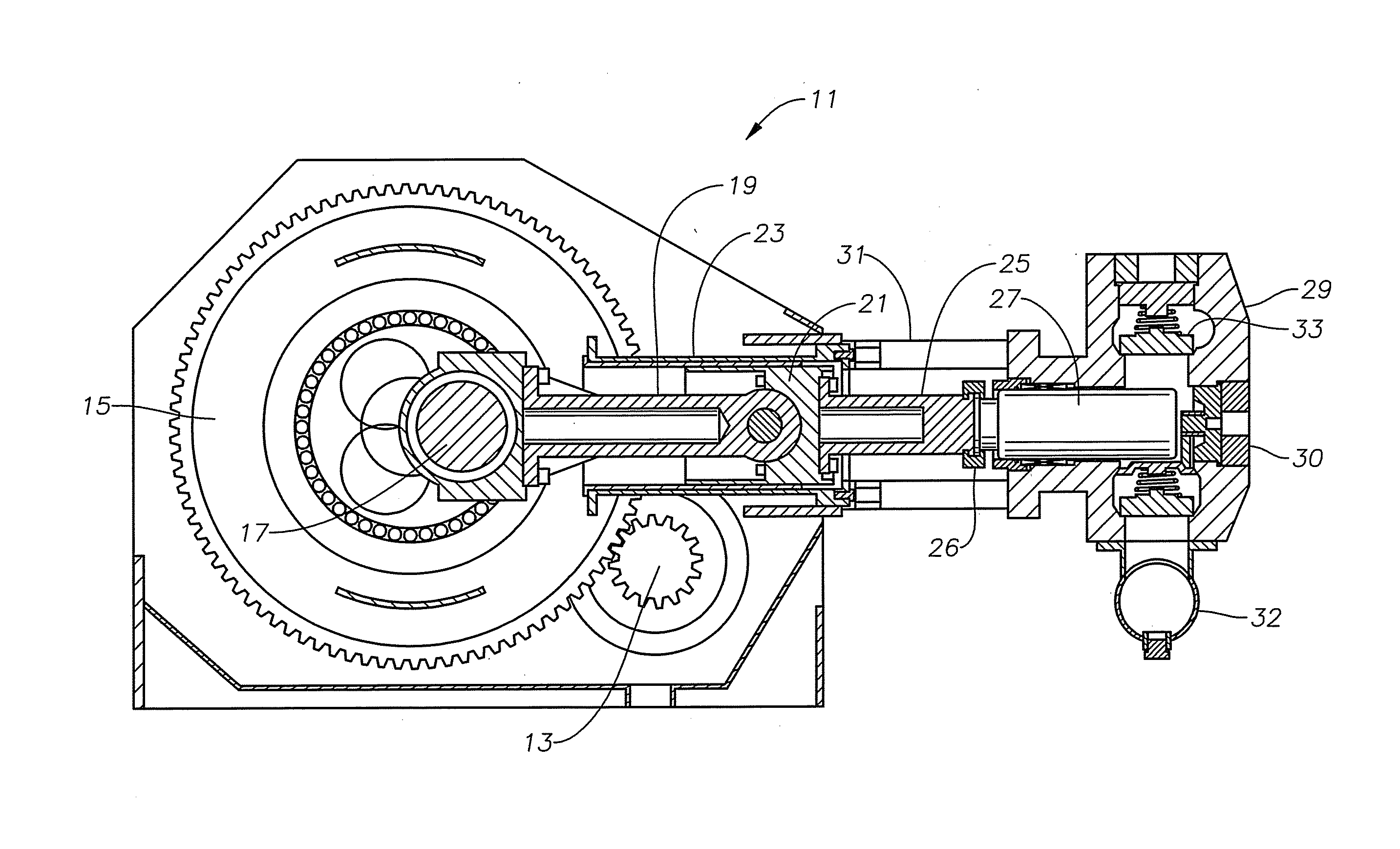
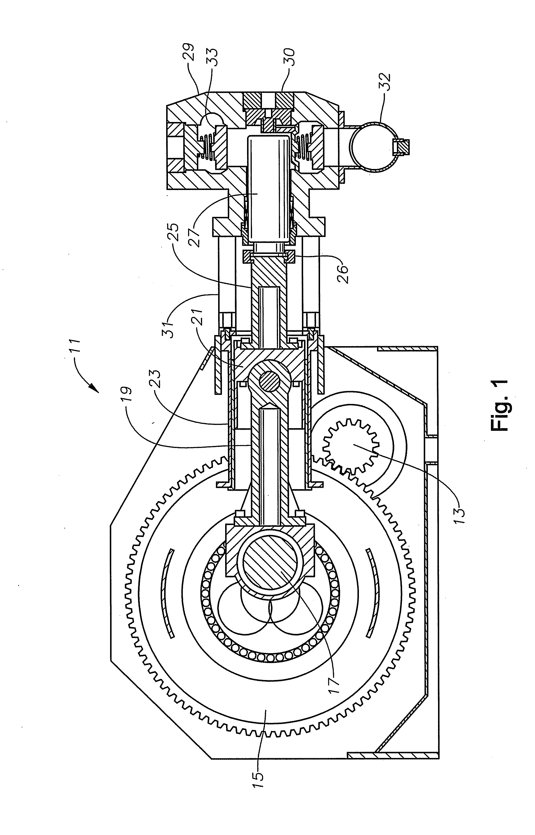
[0016]Referring to FIG. 1, pump 11 is of a type typically utilized for oil and gas well service operations, such as pumping high pressure fluid into a well to hydraulically fracture the well. Pump 11 may also be configured for pumping drilling fluid into the well bore during drilling. Pump 11 is a reciprocating pump having a power source connected to a pinion gear 13, such as an electrical motor or diesel engine. Gear 13 drives a bull gear 15, which is connected to a crankshaft 17. Several connecting rods 19 (only one shown) have aft ends rotatably mounted to crankshaft 17. The terms “aft” and “forward” are used herein for convenience only, not in a limiting manner.

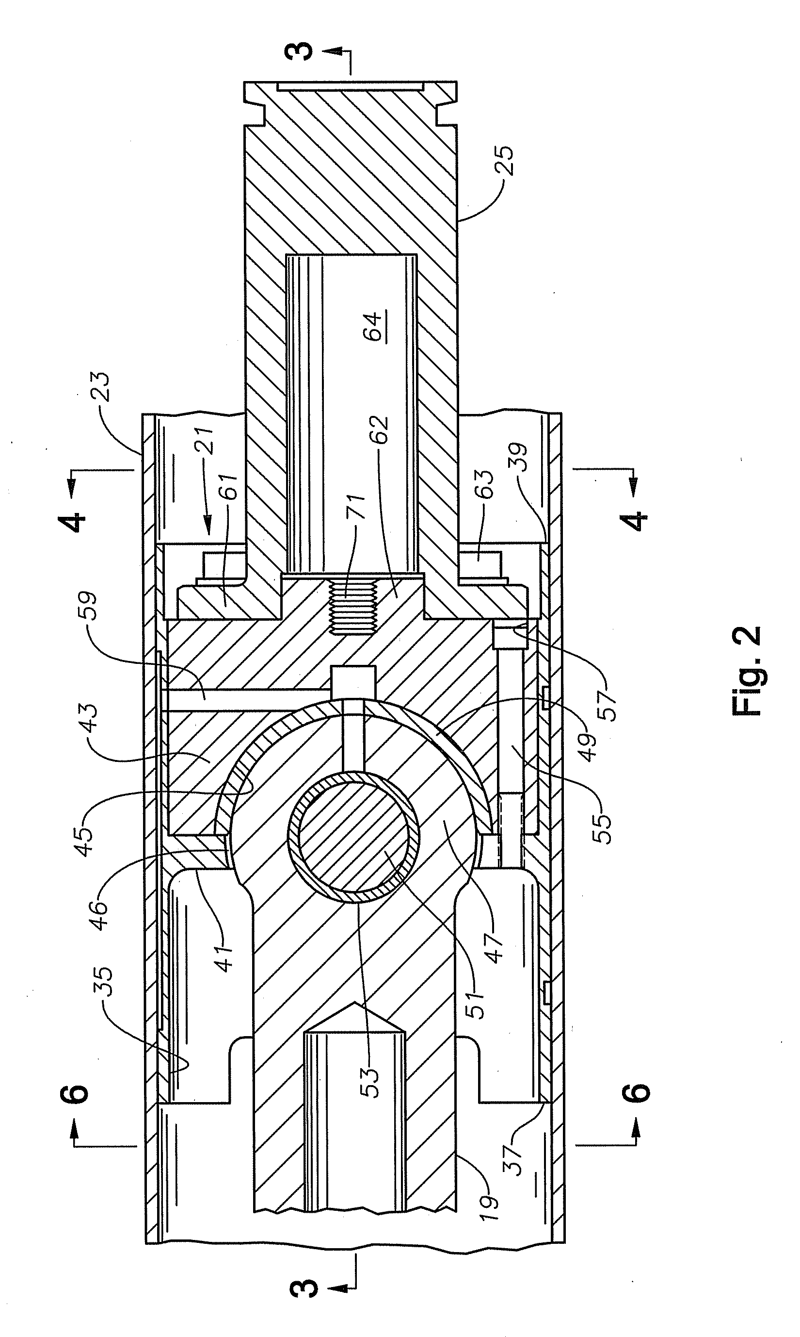
[0017]Each connecting rod 19 has a forward end that is connected to a crosshead 21. Each crosshead 21 strokes linearly within a stationary crosshead case 23, which is mounted to the pump frame. A pony rod 25 secures to the forward end of each crosshead 21, and a plunger 27 connects to the forward end of pony rod 25 by a c...


PUM

PropertyMeasurementUnit
pressuresaaaaaaaaaa
volumesaaaaaaaaaa
pressureaaaaaaaaaa

Abstract

A reciprocating pump has a driven crankshaft and a connecting rod having an aft end rotatably mounted to the crankshaft. The pump has a stationarily mounted crosshead case in which a crosshead assembly strokes. The crosshead assembly has first and second crosshead members. A retainer pivotally joins the forward end of the connecting rod to the first crosshead member. The second crosshead member has a partially cylindrical recess containing a bushing. The forward end of the connecting rod is in pivotal engagement with the bushing. The second crosshead member is releasably secured to the first crosshead member to allow removal of the second crosshead member and the bushing from the crosshead case without detaching the forward end of the connecting rod from the first crosshead member.

Description

CROSS-REFERENCE TO RELATED APPLICATION[0001]This application claims priority to provisional application Ser. No. 61 / 219,521, filed Jun. 23, 2009.FIELD OF THE INVENTION[0002]This invention relates in general to oilfield reciprocating pumps, and in particular to a crosshead between a connecting rod and pony rod that is readily removable.BACKGROUND OF THE INVENTION[0003]One type of reciprocating pump is employed for fracturing oil and gas wells. During a fracturing operation, a series of frac pumps convey large volumes of fluid into the well. The fluid typically comprises water containing proppants, such as sand. The frac pumps are capable of high pressures, such as 15,000 psi, for causing the earth formation to crack or fracture. The proppants flow into the cracks to prop them open when the pressure is removed.[0004]A typical frac pump has a crankshaft rotated by a power source, such as an engine. Several connecting rods have ends rotatably mounted to the crankshaft. The opposite end ...

Claims


Application Information

Patent Timeline
Patent Type & Authority Applications(United States)
IPC IPC(8): F04B53/14B23P6/00
CPCY10T29/49238F04B53/147
Inventor KUGELEV, VLADIMIR
Owner WEIR SPM
Why Eureka
Try Eureka