Pump apparatus

a technology of pumping apparatus and pump body, which is applied in the direction of machines/engines, transportation and packaging, liquid fuel engines, etc., can solve the problems of deterioration of pump energy loss, and achieve the effect of suppressing pump energy loss

Inactive Publication Date: 2010-12-23
HITACHI ASTEMO LTD
View PDF8 Cites 7 Cited by
  • Summary
  • Abstract
  • Description
  • Claims
  • Application Information

AI Technical Summary

Benefits of technology

[0004]It is, therefore, an object of the present invention to provide a pump apparatus to be devised to solve the above mentioned problems, and to suppress the energy loss of the pump at the straight-ahead running.

Problems solved by technology

The flow rate more than necessary is supplied, and the energy loss of the pump is deteriorated.

Method used


Image

  • Pump apparatus
  • Pump apparatus
  • Pump apparatus

Examples


first embodiment

[0026]Hereinafter, apparatuses according to embodiments of the present invention are described in detail with reference to the drawings. A pump apparatus is applied to a hydraulic (fluid-pressure operated) power steering apparatus which is a steering apparatus of a vehicle, like a conventional apparatus.

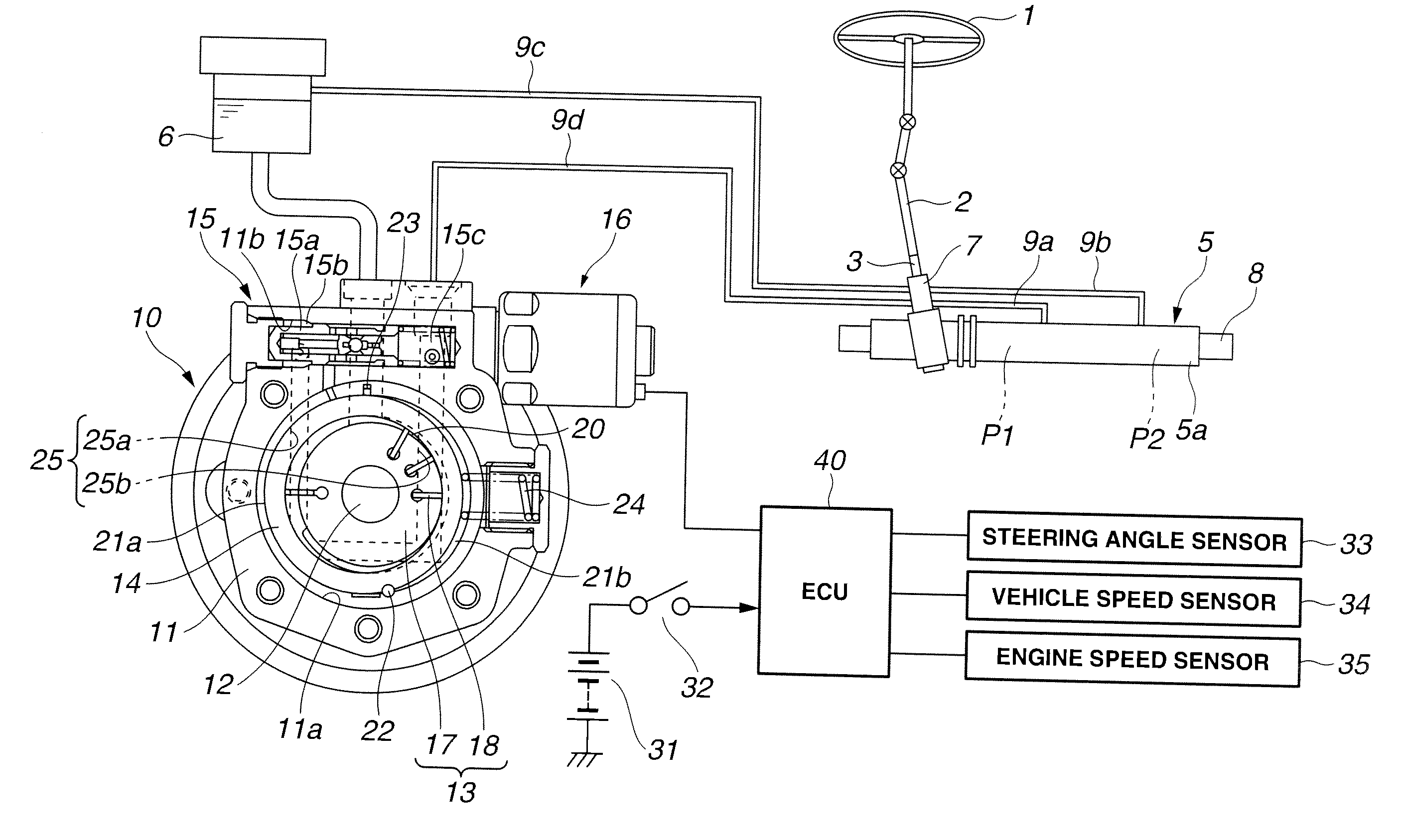
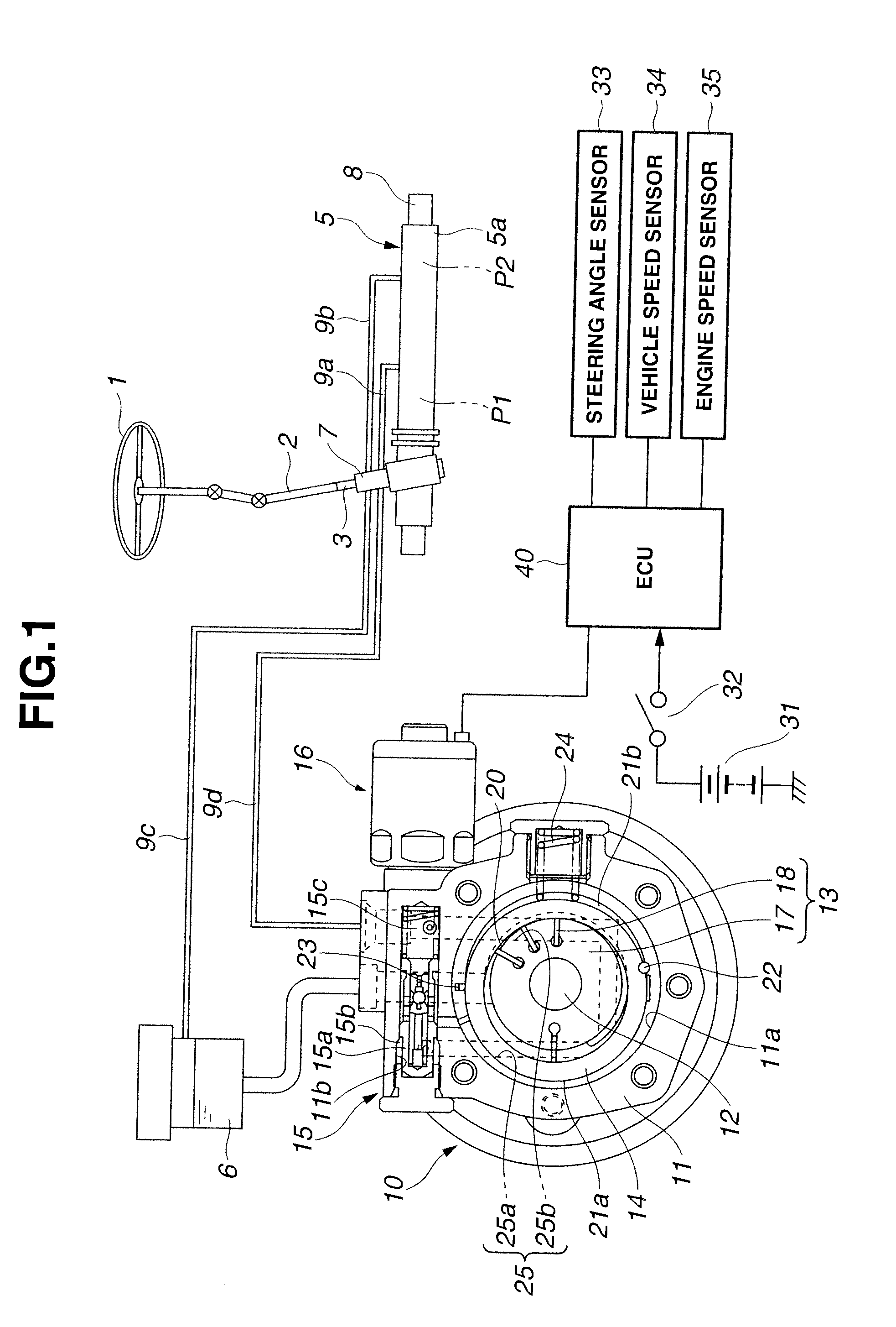
[0027]FIGS. 1-10 show a pump apparatus according to the first embodiment of the present invention. First, a power steering apparatus to which the pump apparatus is applied is illustrated below. As shown in FIG. 1, the power steering apparatus includes an input shaft 2 which has a first end connected with a steering wheel 1 to integrally rotate with steering wheel 1, and a second end, and which is arranged to perform a steering input from a driver (receive a steering input from a driver); an output shaft 3 which has a first end connected with steered wheels (not shown) through a rack and pinion mechanism 4, and a second end connected with the second end of input shaft 2 through a tor...

third embodiment

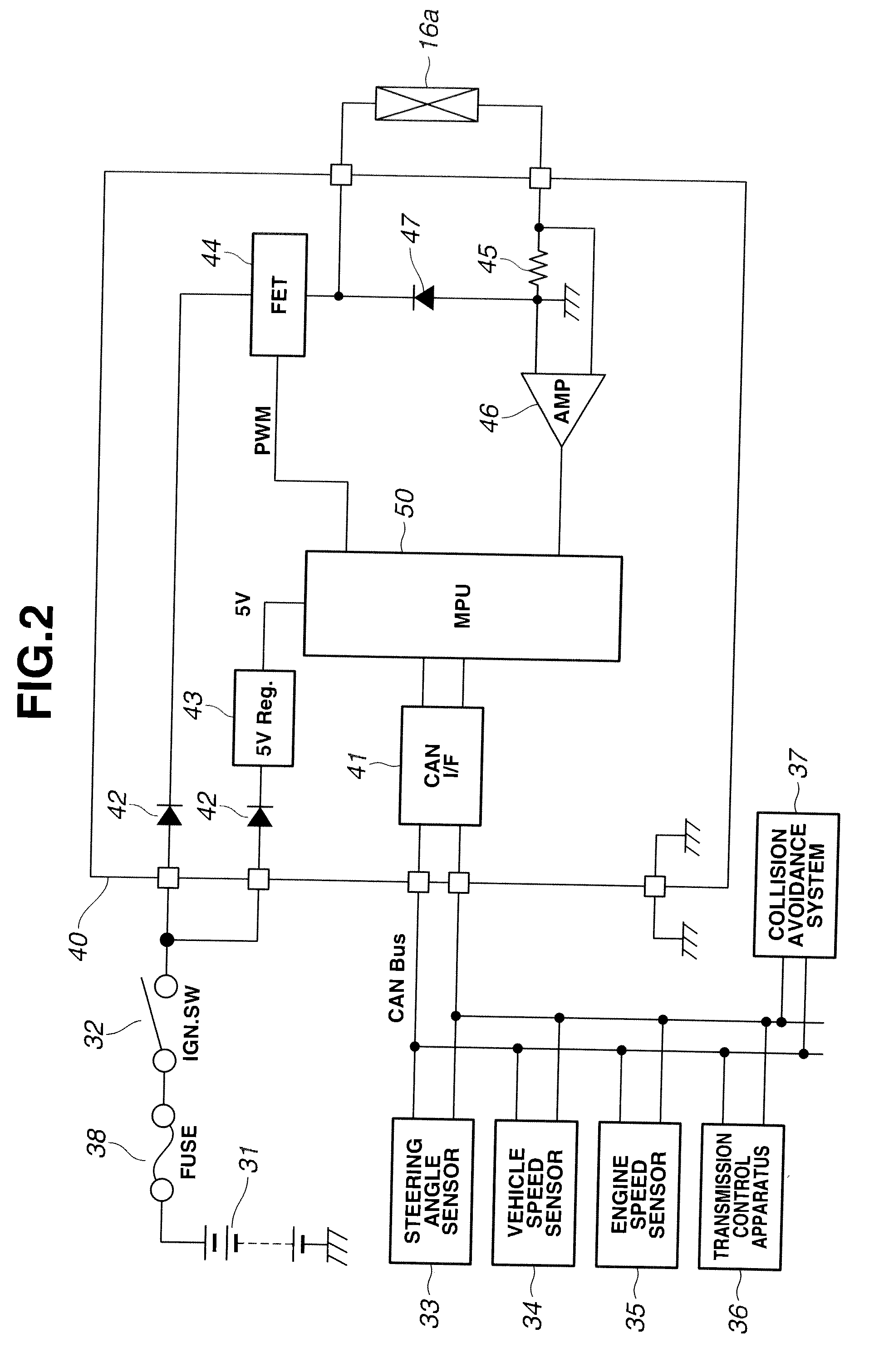
[0094]In this third embodiment, MPU 50 performs an initialization at step S701. Subsequently to step S701, MPU 50 reads actual supply current Ireal flowing through coil 16a at step S702. Subsequently to step S702, MPU 50 reads steering angle θ at step S703. Subsequently to step S703, MPU 50 calculates steering angular speed ω based on steering angle θ at step S704. Subsequently to step S704, MPU 50 calculates steering angular acceleration ωd based on steering angular speed ω at step S705. Subsequently to step S705, MPU 50 reads vehicle speed V at step S706.

[0095]Subsequently to step S706, at step S707, MPU 50 determines target discharge flow rate Qθ—CMD which is dependent on steering angle θ, from the steering angle-target discharge flow rate map (cf. FIG. 6), based on steering angle θ read at step S703. Subsequently to step S707, at step S708, MPU 50 determines target discharge flow rate Qω—CMD which is dependent on steering angular speed ω, from the steering angular speed-target d...


PUM


Abstract

A pump apparatus includes a pump housing; a drive shaft; a pump element; a cam ring arranged to vary an inherent discharge amount based on the eccentric amount of the cam ring; a steering state sensing section configured to sense or estimate a steering angle, a steering angular speed or a steering angular acceleration, and to output the steering angle, the steering angular speed or the steering angular acceleration as a steering state sensing signal; and a solenoid configured to be controlled to suppress the eccentric amount of the cam ring so as to decrease the inherent discharge amount with respect to the steering state sensing signal when the vehicle speed is equal to or greater than a first predetermined vehicle speed, relative to the inherent discharge amount when the vehicle speed is smaller than the first predetermined vehicle speed.

Description

BACKGROUND OF THE INVENTION[0001]This invention relates to an improvement of a pump apparatus used as a hydraulic source of a steering apparatus of a vehicle.[0002]U.S. Pat. No. 6,845,310 (corresponding to Japanese Patent Application Publication No. 2003-285748) discloses a conventional pump apparatus that a steering apparatus for a vehicle employs. This pump apparatus is configured to determine a basic current command value based on a current command value according to a steering angle sensed by a steering angle sensor, a current command value according to a steering angular speed calculated based on the steering angle, and a current command value according to a vehicle speed sensed by a vehicle speed sensor, to add a standby current command value to this basic current command value, and to output the summation of the standby current command value and the basic current command value as a solenoid current command value. A standby flow rate based on the standby current command value ...

Claims


Application Information

Patent Timeline
Patent Type & Authority Applications(United States)
IPC IPC(8): F04C14/22
CPCB62D6/02B62D5/065
Inventor KIMURA, MAKOTO
Owner HITACHI ASTEMO LTD
Why Eureka
Try Eureka