Brace, system and method for forming cementitious structures on a ground surface

a cementitious structure and ground surface technology, applied in the field of cementitious structure formation, can solve the problems of cumbersomeness, difficulty and awkwardness in maintaining the spacing members, and achieve the effect of easy adjustmen

Inactive Publication Date: 2010-12-30
SAVARD NORMAND
View PDF3 Cites 2 Cited by
  • Summary
  • Abstract
  • Description
  • Claims
  • Application Information

AI Technical Summary

Benefits of technology

[0006]An advantage of the present invention is that the brace, system and method thereof allows for anchoring of moulds for forming the structure prior to placement of the moulds on the ground surface.
[0007]Another advantage of the present invention is that the brace, system and method thereof permit positioning of the moulds at a predetermined angular inclination, for example 90 degrees, prior to insertion of any spikes into the ground surface.
[0008]A further advantage of the present invention is that the height and leveling of the moulds relative the ground surface may be easily adjusted, even after the moulds are anchored together.
[0009]Still another advantage of the present invention is that the forming of the cementitious structure is achieved with relatively little manipulation of material or tools, compared to the prior art.
[0010]Still another advantage of the present invention is that the forming of the cementitious structure is achieved with relatively little effort and manpower.
[0011]According to a first aspect of the present invention, there is provided a system for forming a cementitious structure extending on a ground surface, the system comprising:

Problems solved by technology

Unfortunately, the forming of the cementitious structure described above presents a number of disadvantages.
For example, to anchor the moulds to one another, the spikes must first be driven through the moulds and into the ground and then the wires attached while at the same time, and rather cumbersomely, maintaining the spacing members in position.
Further, as the spikes must already be driven into the ground through the moulds to anchor the moulds to one another, adjusting the level of the moulds relative the ground surface and their position relative one another requires manipulation of the moulds with the spikes already inserted therethrough, which is difficult and awkward.

Method used


Image

  • Brace, system and method for forming cementitious structures on a ground surface
  • Brace, system and method for forming cementitious structures on a ground surface
  • Brace, system and method for forming cementitious structures on a ground surface

Examples


Embodiment Construction

[0028]With reference to the annexed drawings the preferred embodiments of the present invention will be herein described for indicative purpose and by no means as of limitation.

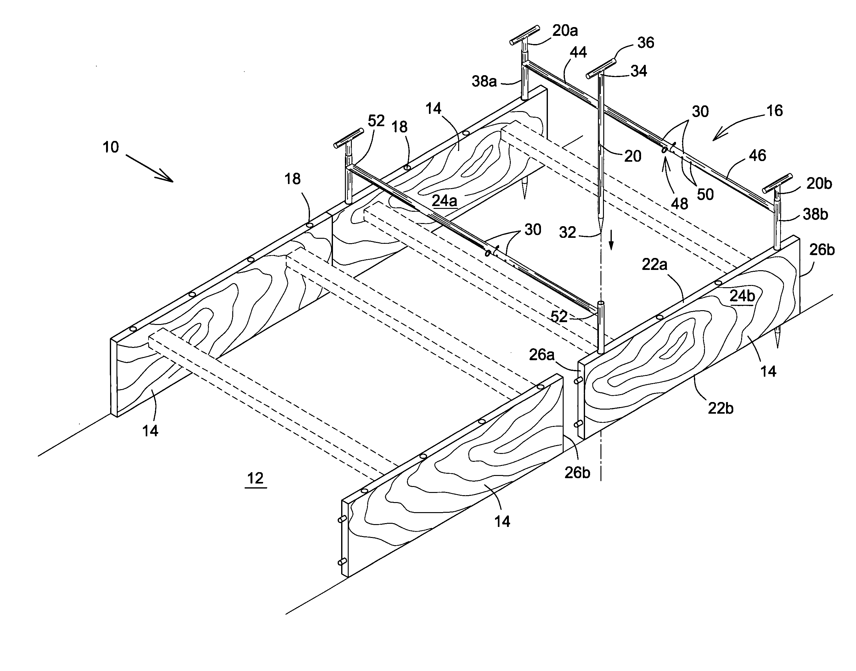
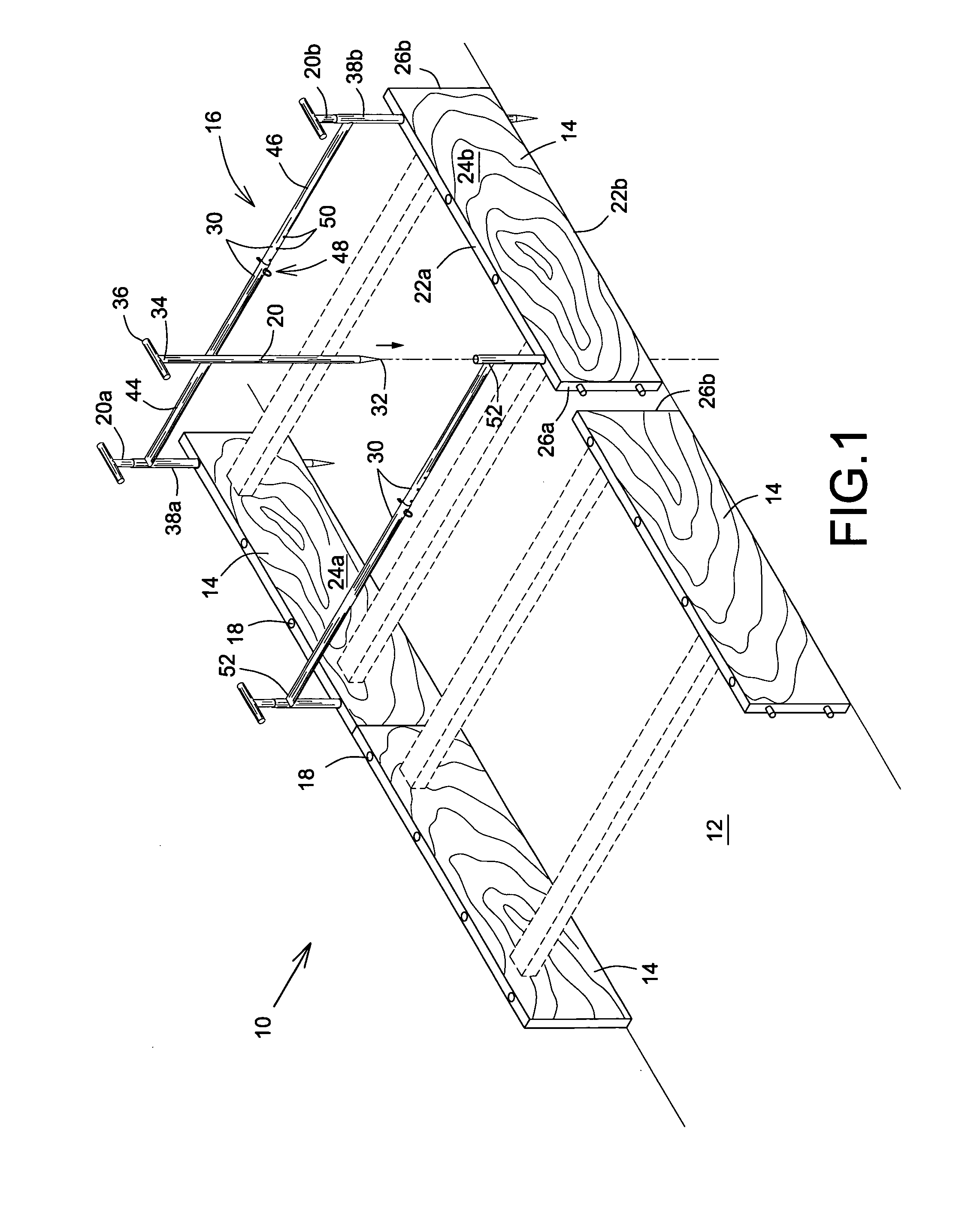
[0029]Referring to FIGS. 1 and 2, there is shown an embodiment of a system, shown generally as 10, for forming a cementitious structure, not shown, on a ground surface 12 in accordance with an embodiment of the present invention. The cementitious structure may be any cementitious structure which is typically formed over a ground surface 12, for example, a sidewalk, road curb, walkway, or the like.

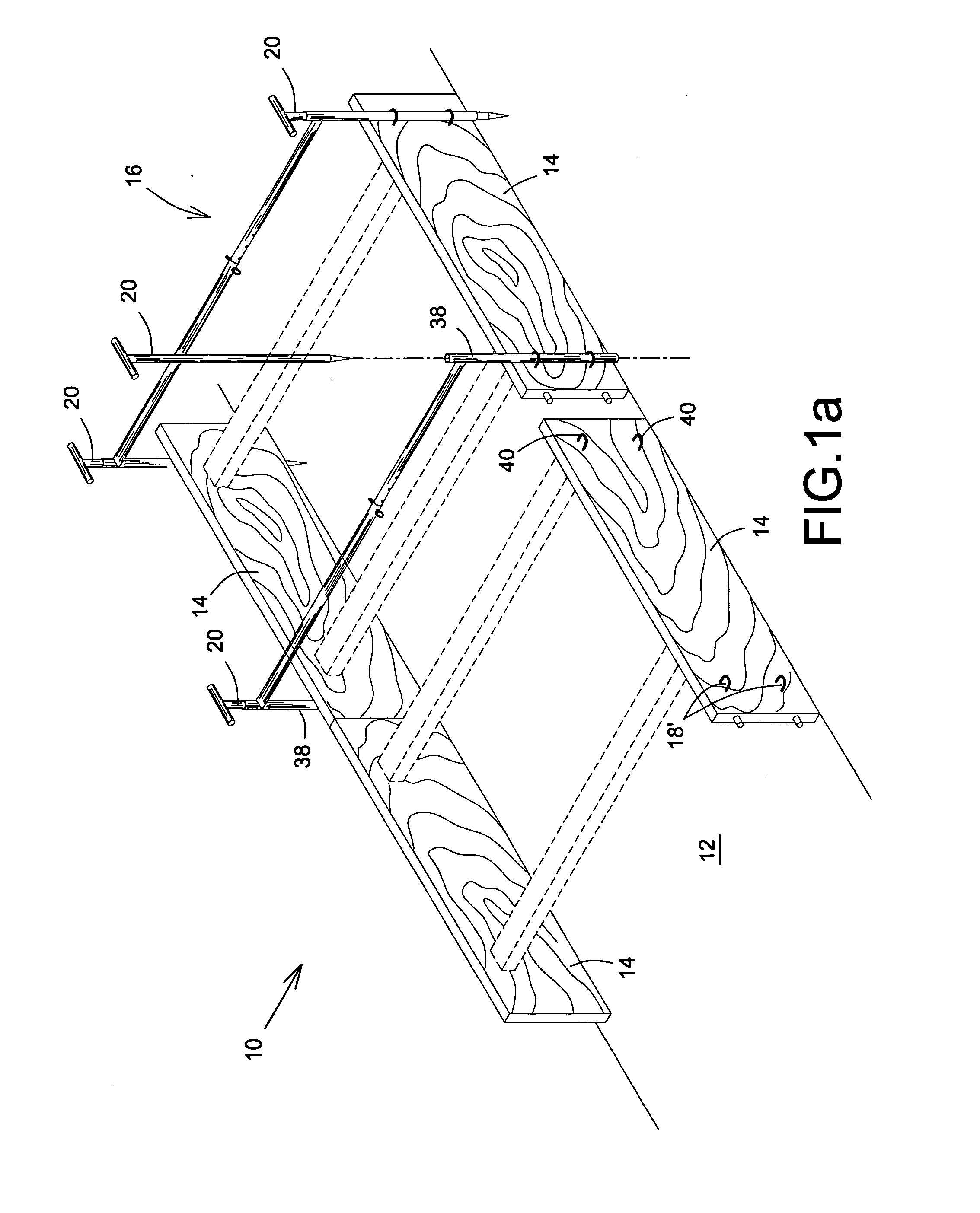
[0030]Generally speaking, and as shown in FIGS. 1, 1a, and 2, the system 10 includes at least one pair of moulds 14 and, for each pair of moulds, at least one brace, shown generally as 16. Each mould 14 of each pair has at least one respective brace pathway 18, 18′ defining a pathway from a top side 22a to a bottom side 22b of the mould 14, and between which an inner and outer wall 24a, 24b of the mould 14 extend. Ho...


PUM

PropertyMeasurementUnit
cementitious structureaaaaaaaaaa
distanceaaaaaaaaaa
lengthaaaaaaaaaa

Abstract

A system for forming a cementitious structure of cementitious material on a ground surface is provided. The system consists of at least one pair of moulds, each mould having at least one pathway disposed thereon, and at least one brace having two spikes connected to one another by a connecting member. The spikes are inserted into the pathways to space the moulds apart, via the connecting member, in fixed spatial relationship and then into the ground surface to anchor the moulds thereto. The cementitious material is then poured between the moulds to form the cementitious structure. Optionally, the spikes may be connected to the connecting member by inserting of spikes into tubes connected to the connecting member, the tubes being insertable into pathways and the spikes subsequently inserted therethrough to insert the spikes through the pathway and into the ground surface.

Description

FIELD OF THE INVENTION[0001]The present invention is related to forming cementitious structures, and is more particularly directed to a brace, system, and method for forming cementitious structures on a ground surface.BACKGROUND OF THE INVENTION[0002]Moulds and braces, and systems and methods therefor, for forming cementitious structures on ground surfaces, for example sidewalks or walkways on the ground surface, are well known in the art. Typically, such methods and systems involve at least two spaced apart moulds which are placed on the ground surface, with spacing members, for example wood blocks shown in stippled lines in FIG. 1, placed in contact with respective inner walls of the moulds. The spacing members maintain the moulds spaced apart from one another and prevent them from falling inwardly toward one another during pouring of the cementitious material to form the structure. To keep the moulds held against the spacing members, spikes are inserted or driven through each mou...

Claims


Application Information

Patent Timeline
Patent Type & Authority Applications(United States)
IPC IPC(8): E01C19/00B29C33/48
CPCE01C19/502B29C33/48
Inventor SAVARD, NORMAND
Owner SAVARD NORMAND
Why Eureka
Try Eureka